
A magnetic pole lead fixing structure for high-speed synchronous motor

A technology of synchronous motor and fixed structure, applied in the direction of electric components, electrical components, electromechanical devices, etc., can solve the problems of potential safety hazards and inconvenience, and achieve the effect of saving installation man-hours, simple installation and operation, and easy installation

Pending Publication Date: 2019-01-18
HARBIN ELECTRIC POWER EQUIP
View PDF0 Cites 0 Cited by
  • Summary
  • Abstract
  • Description
  • Claims
  • Application Information

AI Technical Summary

Problems solved by technology

[0003] The present invention provides a structure with simple structure, novel and reasonable design, and high-speed synchronous motor rotor magnetic pole lead fixing structure with good use effect, which solves the problems of inconvenient dismantling and maintenance and potential safety hazards in the prior art, reduces costs, and improves the utilization rate of raw materials

Method used


Image

  • A magnetic pole lead fixing structure for high-speed synchronous motor
  • A magnetic pole lead fixing structure for high-speed synchronous motor

Examples


Embodiment Construction

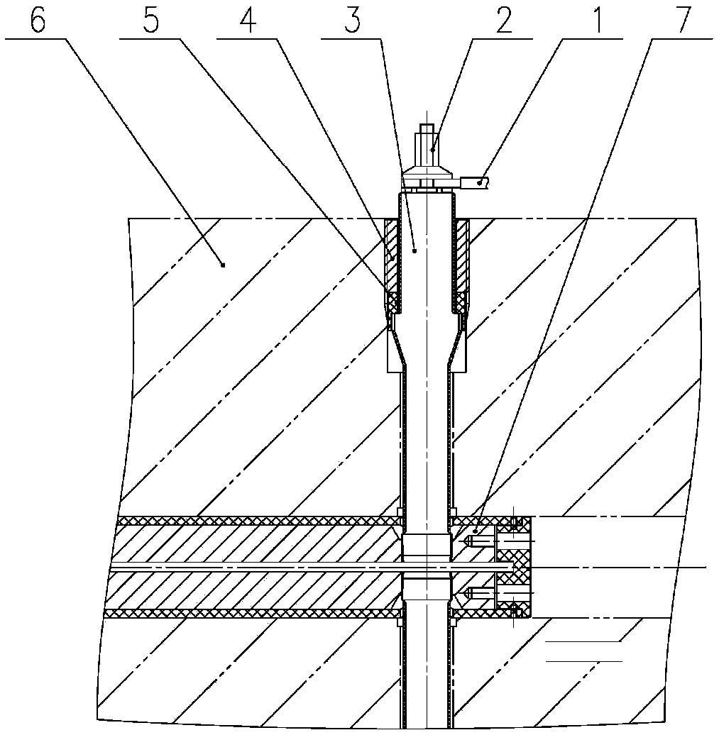
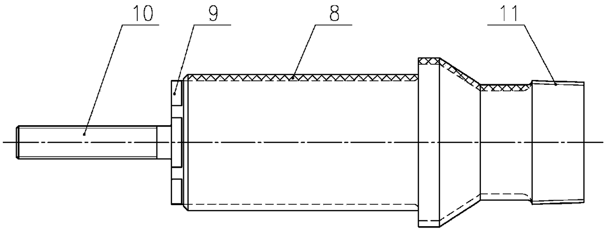
[0014] Such as figure 1 As shown, a high-speed synchronous motor rotor pole lead fixing structure is characterized in that: the conductive screw 3 is connected with the conductive rod assembly 7 arranged in the axial through hole of the rotating shaft 6 through the tapered thread 11, and the conductive screw 3 is connected through the threaded sleeve 4 1. The insulating sleeve 5 is fixed in the radial hole of the rotating shaft 6, the rotor magnetic pole lead wire 1 is fixed on the conductive screw rod 3 through the lock nut 2, and the lock nut 2 is electrically connected with the rotor magnetic pole lead wire 1. The conductive screw 3 wraps the insulating layer 8; the conductive screw 3 is electrically connected to the conductive rod assembly 7 and the rotor magnetic pole lead 1 respectively; figure 2 As shown, the conductive screw rod 3 is provided with: an outer hexagon 9, a common thread 10, and a taper thread 11. The insulating sleeve 5 is pressed onto the conductive sc...


PUM


Abstract

A magnetic pole lead fixing structure for a high-speed synchronous motor is disclosed. The conductive screw 3 is connected to the conductive rod assembly 7 provided in the axial through hole of the rotating shaft 6 by means of a tapered screw 11, the conductive screw 3 is fixed in the radial hole of the rotating shaft 6 by means of a threaded sleeve 4 and the insulating sleeve 5, and the rotor pole lead 1 is fixed on the conductive screw 3 by means of a lock nut 2, a lock nut 2 is electrically connected to the rotor pole lead 1. The invention solves the safety hidden trouble that exists in theprior art because the conductive screw is screwed into the conductive rod with insufficient depth, solves the problem that the poor contact may be caused by the conductive copper gasket in the priorart structure, and solves the safety hidden trouble that the conductive rod in the prior art cannot bear the large centrifugal force when the motor is running at high speed. The invention also solvesthe problem that the conductive rod in the prior art can not bear the centrifugal force. The invention has the advantages of simple installation, high safety, low cost, high utilization rate of raw materials and good use effect. The magnetic pole lead fixing structure has the advantages of simple structure, reasonable design, good conductive insulation effect, large centrifugal force, and convenient disassembly and repair.

Description

technical field [0001] The invention relates to a fixing structure for a magnetic pole lead wire of a high-speed synchronous motor. Background technique [0002] In the known technology, the fixation of the magnetic pole leads of the synchronous motor rotor has always been composed of conductive screws, insulating layers, copper gaskets, insulating gaskets, locking mechanisms and the like. Such a structure usually has the following defects: 1) the structure of the conductive screw screwed into the conductive rod is complex and inconvenient to operate, and it is not easy to disassemble and maintain; This structure has potential safety hazards in terms of strength; 3) The contact between the magnetic pole lead wire and the conductive screw rod conducts electricity through a copper gasket, which is prone to poor contact, making the conductive effect poor. Contents of the invention [0003] The invention provides a high-speed synchronous motor rotor magnetic pole lead fixing ...

Claims


Application Information

Patent Timeline
IPC IPC(8): H02K3/51
CPCH02K3/51
Inventor 徐立敏仲维滨阚旭杨旭东姜旭东刁国鑫王涛张贵滨陈润年李俊亭巩魁鑫陈建国李海鹏
Owner HARBIN ELECTRIC POWER EQUIP
Learn More