
Fixing-point stiffness testing method of front and rear covers of automobile

A test method and fixed point technology, applied in the field of vehicle inspection, can solve the problems of inconvenient operation, high labor intensity, human error, etc., and achieve the effect of ensuring accuracy, high degree of automation, and ensuring safety

Inactive Publication Date: 2019-01-18
ZHAOQING UNIV
View PDF3 Cites 6 Cited by
  • Summary
  • Abstract
  • Description
  • Claims
  • Application Information

AI Technical Summary

Problems solved by technology

In the existing measurement method, by manually reading the value of the dial indicator and drawing the deflection curve, the workload is heavy and it is easy to cause human error. At the same time, the displacement measurement system and the stress measurement system are completely independent, and the experimenter needs to measure and process them separately. Two types of data, labor-intensive and inconvenient to operate
[0005] In the prior art, there is already a static stiffness test bench for the fixed point of the vehicle body, which is used for testing the static stiffness of the body-in-white of the research vehicle, simulating the constraints and load conditions in the actual working process, and used for testing the installation and fixing of the vehicle body. Static point stiffness can also be used to test the dent resistance of sheet metal parts on the outer surface of the car body, but only a test bench is disclosed in the prior art, and there is no specific stiffness test method for different parts of the car

Method used


Image

  • Fixing-point stiffness testing method of front and rear covers of automobile
  • Fixing-point stiffness testing method of front and rear covers of automobile

Examples


Embodiment 1

[0045] Step 1. Fix the car body-in-white: According to the restraint requirements of the front and rear covers of the car during the rigidity test of the fixed points of the front and rear covers of the car during the CAE analysis, adjust the restraint tooling so that the fixed restraint points of the front and rear covers of the car are consistent with the CAE analysis. Here, the body-in-white of the car is fully restrained using the body fixing bracket.

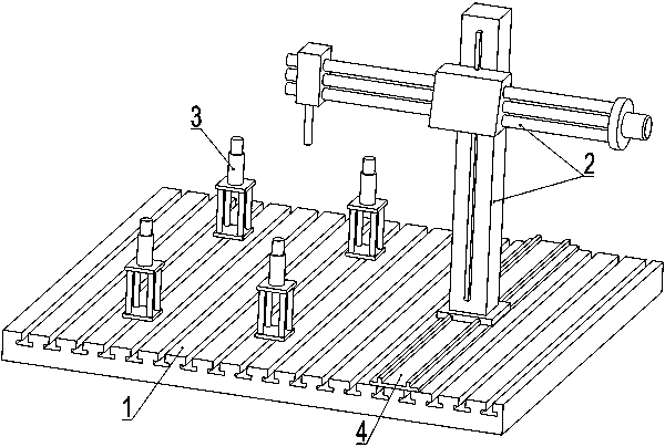
[0046] Step 2. Test preparation: Install the loading electric cylinder for the rigidity test of the fixed point of the front and rear covers of the car as a servo-driven loading unit, and arrange the loading electric cylinder and sensors according to the position and number of loading points during CAE analysis. The loading electric cylinder is connected with the loading rod, and the loading point is loaded through the loading rod, and the force sensor and the displacement sensor are installed on the loading rod. Select a l...


PUM


Abstract

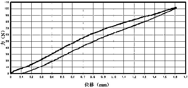
The invention relates to a fixing-point stiffness testing method of front and rear covers of an automobile, and belongs to the technical field of vehicle detection. A stiffness testing platform of thefront and rear covers is used for testing. The method includes the specific steps of: firstly restraining a vehicle body-in-white; then installing a loading electric cylinder of fixing-point stiffness testing of the front and rear covers of the automobile to use the same as a servo drive loading unit; carrying out loading testing of X, Y and Z directions on the front and rear covers according toa preset loading scheme of a control system, wherein different loading schemes are selected and used according to different automobile models and different models of front and rear covers of automobiles; making force-displacement stiffness performance curves of a loading process and an unloading process according to collected force and displacement data after loading completion, and obtaining a residual deformation amount at the same time; and checking equipment normality after testing completion, and then turning off the equipment according to a reverse order of a starting-up order. In testing of the invention, tension loading and pressure loading of the three directions are carried out on hinging points of the front and rear covers, stiffness testing can be carried in an omnidirectionalmanner on the hinging points of the front and rear covers, and accuracy of testing is improved.

Description

technical field [0001] The invention relates to a method for testing the rigidity of a fixed point of a front and rear cover of an automobile, belonging to the technical field of vehicle detection. Background technique [0002] In order to ensure the driving safety of the car, when a new model is developed or a new car is produced, it is necessary to test the static stiffness of the parts on the body to observe the pressure and tension of these parts under different loads and directions. The deformation that occurs and the maximum pressure and tension it can withstand. [0003] The front and rear covers of the car, that is, the hood and trunk cover of the car, are hinged with the main body bracket of the car body. The good stiffness of the hinge point between the front and rear covers of the car and the main body bracket of the car body is the prerequisite for ensuring the long-term stable operation of the front and rear covers of the car. . Therefore, it is necessary to c...

Claims


Application Information

Patent Timeline
Patent Type & Authority Applications(China)
IPC IPC(8): G01M5/00G01M13/00
CPCG01M5/005G01M13/00
Inventor 朱天军郑红艳蔡超明李剑英许锦辉李飞贺勤政李修宜
Owner ZHAOQING UNIV
Learn More