Latching device for vehicle

A latching device and latching technology are applied in vehicle locks, building locks, applications of locks, etc., which can solve the problems of opening sliding doors, engaging and disengaging latches and pawls, etc., and achieve the effect of firm engagement

Active Publication Date: 2019-01-18
HONDA MOTOR CO LTD
View PDF6 Cites 5 Cited by
  • Summary
  • Abstract
  • Description
  • Claims
  • Application Information

AI Technical Summary

Problems solved by technology

Therefore, in the structure of Japanese Unexamined Patent Publication No. 2008-101336, due to the difference in the direction of the load applied to the sliding door for a vehicle, the sliding door for a vehicle may not move in the vehicle width direction but move obliquely, causing the latch and the pawl to disengagement, causing the sliding door to open

Method used


Image

  • Latching device for vehicle
  • Latching device for vehicle
  • Latching device for vehicle

Examples


Embodiment Construction

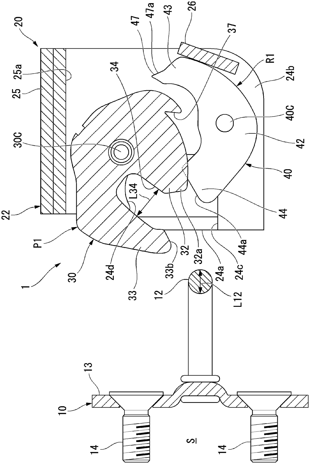
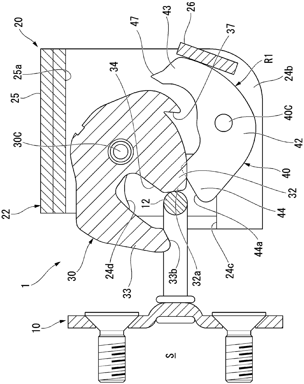
[0023] One embodiment of the present invention will be described in detail with reference to the drawings as appropriate. The same symbol is assigned to the same constituent element, and repeated explanations are omitted.

[0024] Such as figure 1 As shown, a door opening S1 is opened on the side surface of the vehicle body S on which the vehicle latch device 1 according to the present embodiment is installed, and the door opening S1 is opened and closed by a sliding door S2.

[0025] The sliding door S2 slides back and forth along the outer surface on the outer surface of the vehicle body S, and is fitted into the door opening S1 located at the front end of the sliding range to close the door opening S1. Therefore, the sliding door S2 is provided so as to enter obliquely from the rear of the vehicle outer side toward the vehicle inner side when fitted in the door opening S1 .

[0026] Furthermore, the vehicle latch device 1 of the present embodiment includes the striker 10 ...


PUM


Abstract

The present invention provides a latching device for a vehicle that prevents detachment of engagement when a load is applied to a sliding vehicle door from inner side to the outer side of the vehicle,thus restraining the sliding vehicle door and holding the sliding vehicle door under a status of closing the opening portion of the vehicle door. The latching device has a latching member supported to be rotatable between a restraining position of the restrained portion that restrains the striker and a released position at which the restrained portion is released, and a pawl member that is supported to be capable of being restrained Restrict the movement between the disengaged positions, wherein the restriction position is a position that restricts the movement of the latch member to the release position, and the restriction release position is a position separated from the movement trajectory of the latch member. The latch member has an engagement recess formed with a tooth surface thatintersects with a tangential direction of the outer peripheral portion. The pawl member includes an engagement arm portion having a locking claw and a movement restricting portion located on the otherside of the pawl shaft with respect to the engagement arm portion. The engaging arm portion is set to have a weight distribution larger than the weight of the movement restricting portion.

Description

technical field [0001] The present invention relates to a latch device for a vehicle that locks and unlocks a sliding door that opens and closes a door opening by sliding. Background technique [0002] Conventionally, the movement of the sliding door is restricted so that the sliding door does not accidentally open when a load is applied to the sliding door from the interior of the vehicle to the exterior of the vehicle. [0003] For example, Japanese Patent Application Laid-Open No. 2008-101336 proposes a structure of a latch device including a latch that is engaged with a striker disposed on the vehicle body when an impact is input, and a latch that is engaged with a striker disposed on the vehicle body. Engaging pawls. [0004] The sliding door for a vehicle is configured to slide on the outer side of the vehicle body, and to enter obliquely with respect to the door opening when the door opening is closed. Therefore, in the structure of Japanese Patent Application Laid-...

Claims


Application Information

Patent Timeline
IPC IPC(8): E05B83/40E05B77/14E05B85/00E05B85/04E05B85/24
CPCE05B77/14E05B83/40E05B85/00E05B85/04E05B85/24
Inventor 新宫启司源平造渡边健大
Owner HONDA MOTOR CO LTD
Why Eureka
Try Eureka