Novel bridge expansion joint device for monitoring displacement of beam end

A technology for expansion joints and monitoring beams, which is applied to measuring devices, bridges, bridge parts, etc., can solve problems such as inability to monitor beam end displacement, identify self-damage, increase the impact of vehicle loads on bridges, and reduce bridge service life. Achieve the effect of reducing operation and maintenance costs, reducing adverse effects and low costs

Active Publication Date: 2019-01-18
SOUTHEAST UNIV
View PDF6 Cites 8 Cited by
  • Summary
  • Abstract
  • Description
  • Claims
  • Application Information

AI Technical Summary

Problems solved by technology

[0004] Once the expansion joint is damaged, it will increase the impact of the vehicle load on the bridge. If it is not detected early, it will accelerate the damage of the bridge deck pavement and reduce the service life of the bridge.
However, most active bridge expansion joints have a single function and a low degree of intelligence, which makes it impossible to monitor beam end displacement and identify self-damage

Method used


Image

  • Novel bridge expansion joint device for monitoring displacement of beam end
  • Novel bridge expansion joint device for monitoring displacement of beam end
  • Novel bridge expansion joint device for monitoring displacement of beam end

Examples


Embodiment Construction

[0023] The present invention will be further explained below in conjunction with the accompanying drawings and specific embodiments. It should be understood that the following specific embodiments are only used to illustrate the present invention and are not intended to limit the scope of the present invention. It should be noted that the words "front", "rear", "left", "right", "upper" and "lower" used in the following description refer to the directions in the drawings, and the words "inner" and "outer ” refer to directions towards or away from the geometric center of a particular part, respectively.

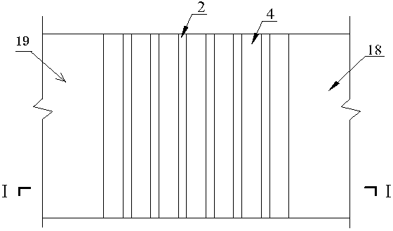
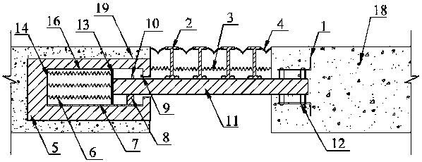
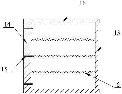
[0024] Such as Figure 1-2 As shown, the supporting beam 11 is connected to the top plate 13 of the distributed displacement measurement system, and the initial deformation of the spring is zero. Under the action of vehicle load, etc., the beam bodies 18 and 19 at both ends undergo relative displacement, and the supporting base 8 moves along the slideway 7 . The support beam ...


PUM


Abstract

The invention discloses a novel bridge expansion joint device for monitoring the displacement of a beam end. The device comprises a beam body 1, a beam body 2, an expansion and contraction system anda distributed displacement measurement system. The invention is connected with the embedded reinforcing bar in the beam body through the C-shaped steel and the U-shaped reinforcing bar on the supporting cross beam. As that beam body at both ends move relative to each other, the supporting beam pushes or stretches the top plate of the distribute displacement measuring system, causing the spring group to produce tension-compression deformation, and the tension-compression sensor can measure the internal force of each spring correspondingly, and convert the displacement of the beam end through awireless data transmission module. The movement of the supporting beam causes the I-shaped middle beam to move on it, and the bird-shaped rubber belt is compressed or stretched to realize the telescopic function. The invention has the advantages of simple structure and convenient installation, and can coordinate and analyze the monitored beam end displacement data with temperature and other data,and serves the bridge health monitoring field, can simultaneously evaluate the service state of the expansion joint, and improves the intelligent level of the bridge expansion joint and the bridge operation management level.

Description

technical field [0001] The invention relates to a novel bridge expansion joint device capable of monitoring beam end displacement, belonging to the technical field of bridge health monitoring. Background technique [0002] Bridge expansion joints can make the beam freely deform according to the design calculation diagram under the influence of temperature change, load action, foundation displacement, concrete shrinkage and creep, while ensuring smooth driving. With the advancement of transportation infrastructure construction, bridges are developing to large spans, which puts forward higher requirements on the performance of bridge expansion joints. The larger the span, the greater the requirement for longitudinal deformation of the beam body. Whether bridge expansion joints can work effectively directly affects traffic safety and driving comfort. The research shows that the cumulative longitudinal displacement of the beam end is an important reason for the premature failu...

Claims


Application Information

Patent Timeline
Patent Type & Authority Applications(China)
IPC IPC(8): E01D19/06G01B21/02
CPCE01D19/062G01B21/02
Inventor 王浩柳家为赵亚宁张一鸣沈惠军
Owner SOUTHEAST UNIV
Why Eureka
Try Eureka