Woodpecker type step-by-step drive device
A technology of stepping transmission and transmission device, which is applied in the field of transmission and transportation, can solve the problems of high maintenance cost and high cost, and achieve the effect of low maintenance cost, low cost and simple control mode
- Summary
- Abstract
- Description
- Claims
- Application Information
AI Technical Summary
Problems solved by technology
Method used
Image
Examples
Embodiment 1
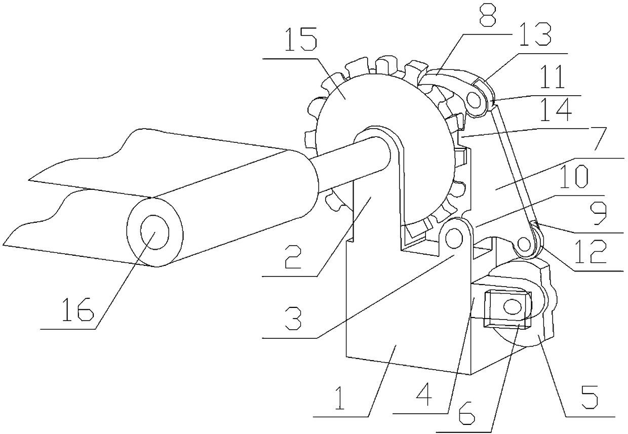
[0029] Embodiment 1, first turn on the rotating motor 6, the rotating motor 6 drives the main rotating cam 5 to rotate, the driven roller 12 on the transmission seat 7 moves up and down with the rotation of the main rotating cam 5, under the action of the lower rotating seat 10, from The moving roller 12 moves up and down so that the entire transmission seat 7 rotates around the lower rotating seat 10. When the main rotating cam 5 turns from the arc surface to the plane, the driven roller 12 will descend, thereby driving the transmission seat 7 to move backward and downward. Then drive the rotating push block 8 to move back and down to enter the next tooth groove, and simultaneously cut into the push block 14 and also withdraw from the tooth groove. When the main cam 5 turns from the plane to the arc surface, the driven roller 12 will follow Ascent, so that the rotating push block 8 is pushed forward and upward through the transmission seat 7, and at the same time, the push blo...
Embodiment 2
[0030] Embodiment 2. In this device, the main rotating cam 5, the transmission seat 7, the gear plate 15 and the roller 16 are all rotatably connected on the mounting base 1, so that misalignment and the like will not occur. The first U-shaped mounting base 2, the second The installation positions of the second U-shaped mounting seat 3 and the third U-shaped mounting seat 4 are designed so that no additional interference will occur to the moving parts in the device, and the lower end of the transmission seat 7 is provided with a mounting groove 8 to rotate and connect the driven roller 12. In the installation groove 8, the driven roller 12 is in contact with the main rotating cam 5, so that the transmission seat 7 can move smoothly, and the rotating push block 8 rotates with the upper transmission seat 11 on the upper end of the transmission seat 7 by setting the installation groove 13 Connected so that the rotating push block 8 can cut into the tooth groove quickly and accurat...
PUM
 Abstract
Description
Claims
Application Information
 - Generate Ideas
- Intellectual Property
- Life Sciences
- Materials
- Tech Scout
- Unparalleled Data Quality
- Higher Quality Content
- 60% Fewer Hallucinations
Browse by: Latest US Patents, China's latest patents, Technical Efficacy Thesaurus, Application Domain, Technology Topic, Popular Technical Reports.
© 2025 PatSnap. All rights reserved.Legal|Privacy policy|Modern Slavery Act Transparency Statement|Sitemap|About US| Contact US: help@patsnap.com


