
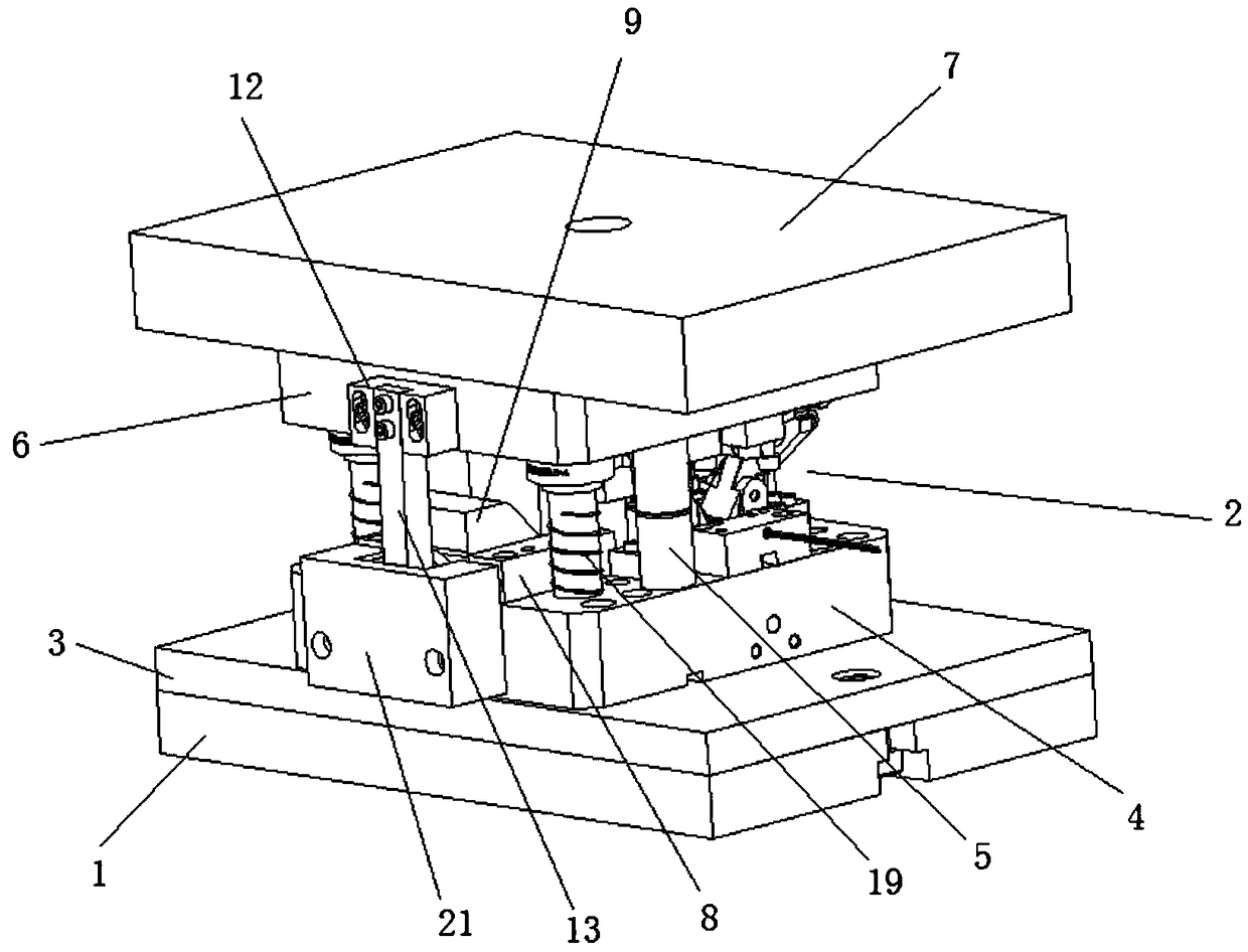
Buckle pushing mechanism used for U-type buckle production

A molding mechanism and buckle technology, applied in the direction of pushing out equipment, etc., can solve the problems affecting the discharge efficiency of the U-shaped buckle, the connecting rod is easy to collide with the upper die seat, etc., and achieves the effect of ensuring normal work and efficiency.

Pending Publication Date: 2019-01-18
黔西南州乐呵化工有限责任公司
View PDF8 Cites 3 Cited by
  • Summary
  • Abstract
  • Description
  • Claims
  • Application Information

AI Technical Summary

Problems solved by technology

[0004] The purpose of the present invention is to solve the problem in the prior art that the connecting rod is easy to collide with the upper die base in the production of U-shaped buckles, thereby affecting the discharge efficiency of the U-shaped buckles, and the proposed U-shaped buckle production push card mechanism

Method used


Image

  • Buckle pushing mechanism used for U-type buckle production
  • Buckle pushing mechanism used for U-type buckle production
  • Buckle pushing mechanism used for U-type buckle production

Examples


Embodiment Construction

[0025] The following will clearly and completely describe the technical solutions in the embodiments of the present invention with reference to the accompanying drawings in the embodiments of the present invention. Obviously, the described embodiments are only some, not all, embodiments of the present invention.

[0026] In describing the present invention, it should be understood that the terms "upper", "lower", "front", "rear", "left", "right", "top", "bottom", "inner", " The orientation or positional relationship indicated by "outside", etc. is based on the orientation or positional relationship shown in the drawings, and is only for the convenience of describing the present invention and simplifying the description, rather than indicating or implying that the referred device or element must have a specific orientation, so as to Specific orientation configurations and operations, therefore, are not to be construed as limitations on the invention.

[0027] refer to Figure ...


PUM


Abstract

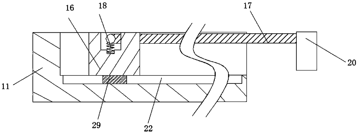
The invention discloses a buckle pushing mechanism used for U-type buckle production. The buckle pushing mechanism comprises an installing plate and a buckle forming mechanism, a lower fixing plate isfixedly connected to the upper surface of the installing plate, a lower die base is fixedly connected to the upper surface of the lower fixing plate, multiple positioning guiding rods are fixedly connected to the upper surface of the lower die base, the rod walls of the positioning guiding rods are sleeved with the same upper die base, an upper fixing plate is fixedly connected to the upper surface of the upper die base, the upper surface of the lower die base and the lower surface of the upper die base are separately fixedly connected with the buckle forming mechanism, two symmetrically distributed fixed slide rails are fixedly connected to the upper surface of the lower die base, and the same advancing and retreating sliding block is in sliding connection to the opposite sides of the two fixed slide rails. It is unnecessary to use an external link mechanism for pushing buckles, it can be avoided that links collide with the upper die base, it is guaranteed that the upper die base cannormally work, and it can be also avoided that when a die does not work, the U-type buckles are inconvenient to discharge; time and labor are saved, and the efficiency of discharging the U-type buckles is guaranteed.

Description

technical field [0001] The invention relates to the technical field of U-shaped buckle production equipment, in particular to a card pushing mechanism for U-shaped buckle production. Background technique [0002] The civil explosives industry is known as "the energy of the energy industry, the foundation of the basic industry". Its downstream demand is mainly concentrated in mining, water conservancy and hydropower, railways and roads and other infrastructure. It is an important and special industry category. Due to recent policy changes With strong support, frequent occurrence of geological disasters and demand for construction, the output value of civil explosive products has grown rapidly. According to the data of the "China Civil Explosive Industry Market Prospect and Investment Strategic Planning Analysis Report" by Qianzhan Enterprise Research Institute, the civil explosive industry has now entered the industry In the mature period of the cycle, the market growth rate ...

Claims


Application Information

Patent Timeline
Patent Type & Authority Applications(China)
IPC IPC(8): B21D45/04B21D28/02
CPCB21D28/02B21D45/04
Inventor 邱远喜袁丁龙杰吴强万涛刘志勇吴仕峰黄智才曹亚军
Owner 黔西南州乐呵化工有限责任公司
Learn More