Pipe Fitting Grooving Device

A technology of groove pressing and pipe fittings, which is applied in the field of pipe fittings processing, can solve problems such as poor stamping stability, and achieve the effects of improving stamping stability, preventing force damage, and avoiding bearing radial force

Active Publication Date: 2020-07-28
QINGDAO ZEHAO AUTO PARTS
View PDF4 Cites 0 Cited by
  • Summary
  • Abstract
  • Description
  • Claims
  • Application Information

AI Technical Summary

Problems solved by technology

[0004] The object of the present invention is to provide a pipe fitting grooving device to solve the technical problem of poor stamping stability in the pipe fitting grooving operation in the prior art

Method used


Image

  • Pipe Fitting Grooving Device
  • Pipe Fitting Grooving Device
  • Pipe Fitting Grooving Device

Examples


Embodiment 1

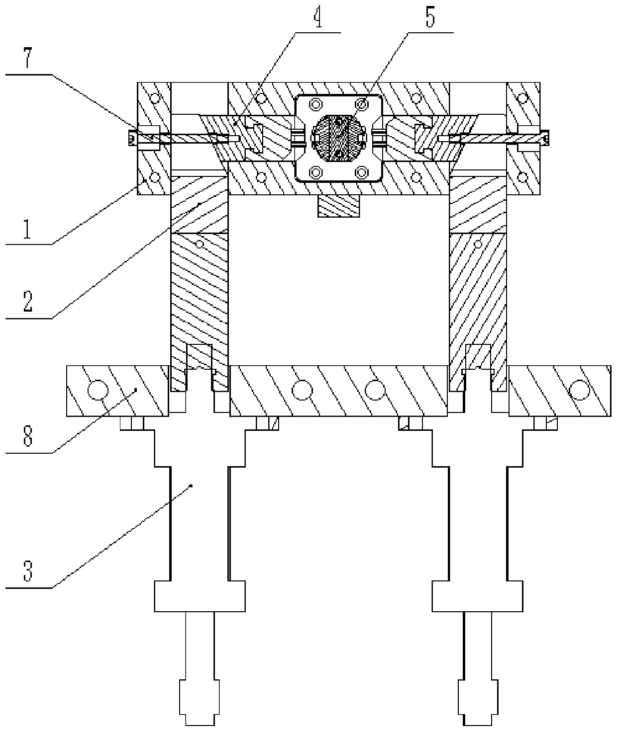
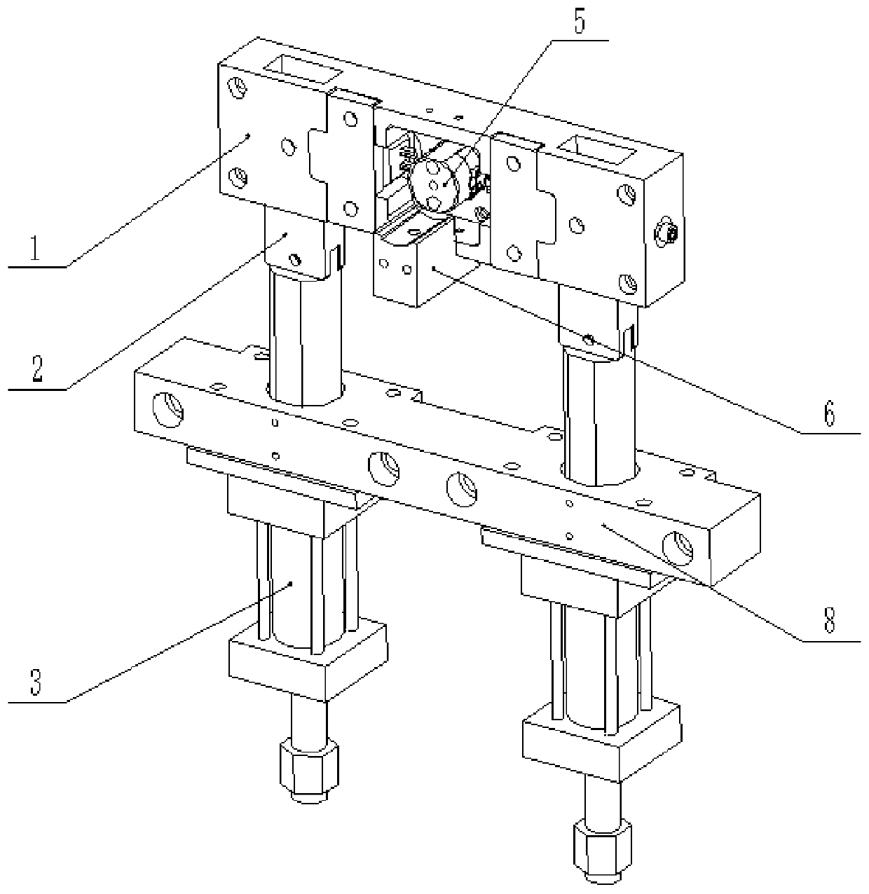
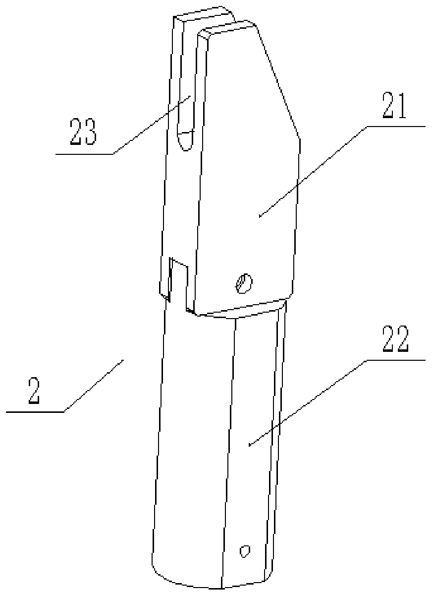
[0031] Such as figure 1 and figure 2 As shown, the pipe fitting grooving device provided by the embodiment of the present invention includes: a frame 1, a push rod 2, a telescopic cylinder 3, a grooving part 4 and a support 5, the push rod 2 is slidably connected to the frame 1, and the telescopic cylinder 3 The movable end of the push rod 2 is connected to the push rod 2, and the groove part 4 is slidably connected to the frame 1, and abuts against the push rod 2. The end face of the push rod 2 and the groove part 4 is opposite from the end close to the telescopic cylinder 3 to the end away from the telescopic cylinder. One end of 3 is inclined in the direction away from the grooved part 4 , and the support part 5 is located on the side of the grooved part 4 away from the push rod 2 and is connected with the frame 1 .

[0032] Specifically, the frame 1 is provided with a first chute and a second chute, the push rod 2 is slidably connected to the first chute, the pressing gr...


PUM


Abstract

The invention provides a pipe fitting rolling groove device, which relates to the technical field of the pipe fitting processing and comprises: a frame, a push rod, a telescopic cylinder, a rolling groove piece and a supporting piece. The push rod is slidably connected to the frame. The free end of the telescopic cylinder is connected to the push rod. The rolling groove piece is slidably connectedto the frame and is connected to the push rod. The end face of the push rod, opposite to the rolling groove piece, inclines, from one end near the telescopic cylinder to the other end deviating fromthe telescopic cylinder, toward the direction deviating from the rolling groove piece. The supporting piece is arranged on the rolling groove piece at one end deviating from the push rod, and is connected to the frame. According to the pipe fitting rolling groove device, the technical problem that the ramming stability of the pipe fitting rolling groove work is poor in the prior art can be solved,thereby improving the ramming stability, and preventing the telescopic cylinder from being damaged by the radial force.

Description

technical field [0001] The invention relates to the technical field of pipe fitting processing, in particular to a pipe fitting grooving device. Background technique [0002] In the processing of office chairs, pipe fittings are usually used to cover the mandrel to form the support shaft. In order to position the pipe fitting and the mandrel in the circumferential direction and prevent the mandrel from coming out of the pipe fitting, pressure is usually applied outside the pipe fitting so that the side wall of the pipe fitting is sunken inward to complete the grooving operation on the pipe fitting. [0003] When grooving pipe fittings, it is usually necessary to use a clamp to fix the pipe fittings, and then use a hydraulic cylinder to stamp the outer wall of the pipe fittings. Since the outer wall of the pipe fittings is a curved surface, the hydraulic cylinder bears a large radial force during the working process, and the stamping stability is poor. And it is very easy to...

Claims


Application Information

Patent Timeline
Patent Type & Authority Patents(China)
IPC IPC(8): B21D43/00B21D17/02
CPCB21D17/02B21D43/003
Inventor 张启旭
Owner QINGDAO ZEHAO AUTO PARTS
Why Eureka
Try Eureka