
A terminal connection structure

A terminal and connection structure technology, applied in the direction of connection, conductive connection, clamping/spring connection, etc., can solve the problems of small conductive contact area, current overload, large temperature rise, etc., to increase the conductive contact area and increase the firmness , the effect of convenient operation

Active Publication Date: 2019-01-15
GUANGZHOU PANYU CABLE WORKS
View PDF6 Cites 8 Cited by
  • Summary
  • Abstract
  • Description
  • Claims
  • Application Information

AI Technical Summary

Problems solved by technology

[0002] It is very important to ensure the safe and stable operation of the power grid in today's society. The poor connection of wires has brought a lot of troubles to people. At present, the conductive connection between the terminal and the equipment terminal is usually directly connected by bolts to the equipment terminal and the wiring. The wire terminal of the terminal is directly fixed and connected. This connection method is prone to the following problems: the operation is time-consuming and inconvenient; These problems will lead to poor contact between equipment terminals and wiring terminals, large interface resistance and large temperature rise, which will lead to current overload operation and bring hidden dangers to power safety

Method used


Image

  • A terminal connection structure
  • A terminal connection structure
  • A terminal connection structure

Examples


Embodiment Construction

[0017] In order to make the object, technical solution and advantages of the present invention clearer, the present invention will be further described in detail below in conjunction with the accompanying drawings and embodiments. It should be understood that the specific embodiments described here are only used to explain the present invention, not to limit the present invention.

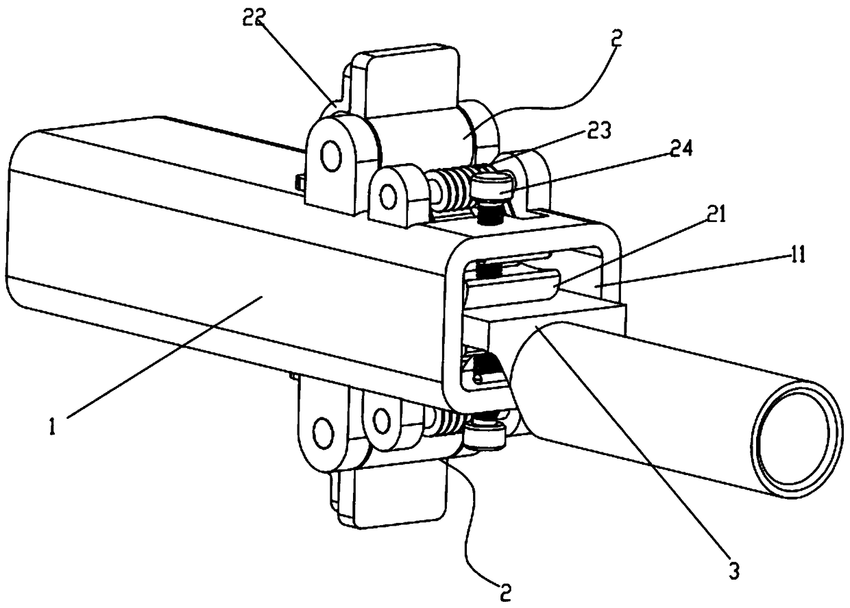
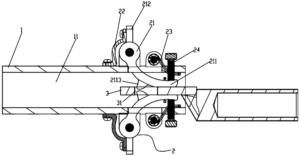
[0018] like Figure 1-5 As shown, a terminal connection structure includes a connection base 1 and two movable chucks 2, the connection base 1 is provided with an insertion hole 11 for the insertion of the connection terminal 3, and the opposite side walls of the insertion hole 11 are respectively provided with There are installation holes 12, and the movable chuck 2 includes a splint 21 and two elastic pressing parts, and the two elastic pressing parts are elastic metal plates 22 and torsion springs 23 respectively, and the splints of the two moving chucks 2 21 respectively pass through the corre...


PUM


Abstract

The present invention relate to the field of power tool, in particular to a terminal connection structure, comprises a connecting seat and a two-action chuck, A plug hole is arranged on the connectingseat, A movable chuck comprises a splint and an elastic pressing member, the splints of the two moving chucks are respectively articulated with the connecting seat, As that two end of the two elasticpressing member abut on the connecting seat and the corresponding splint respectively, the clam ends of the two splints are pressed against each other to clamp the terminal, the clamping end includessuccessively arranged inlet segments, a flat pressure section and an anti-disengagement section, wherein the inlet section is raised in the opposite direction to the pressing direction so as to facilitate insertion of the terminal, the flat pressure section is a planar structure capable of abutting against the pressing of the terminal and forming an electrically conductive contact surface with the terminal, and the anti-disengagement section is provided with barbs inclined in the insertion direction of the terminal for hooking the terminal to prevent disengagement of the terminal; The terminal connection structure has the advantages of convenient operation, firm connection, tight contact of the conductive contact surface and no gap.

Description

technical field [0001] The invention relates to the field of electric tools, in particular to a terminal connection structure. Background technique [0002] It is very important to ensure the safe and stable operation of the power grid in today's society. The poor connection of wires has brought a lot of troubles to people. At present, the conductive connection between the terminal and the equipment terminal is usually directly connected by bolts to the equipment terminal and the wiring. The wire terminal of the terminal is directly fixed and connected. This connection method is prone to the following problems: the operation is time-consuming and inconvenient; These problems will lead to poor contact between equipment terminals and wiring terminals, large interface resistance and large temperature rise, which will lead to current overload operation and bring hidden dangers to electricity safety. Contents of the invention [0003] In order to solve the above problems, the ...

Claims


Application Information

Patent Timeline
Patent Type & Authority Applications(China)
IPC IPC(8): H01R4/48H01R4/36
CPCH01R4/36H01R4/4809H01R4/4863H01R4/489
Inventor 黄应敏胡超强尤占山邵源鹏高伟光刘金勇张仕欢王廷发冯家杰
Owner GUANGZHOU PANYU CABLE WORKS
Learn More