A dual-frequency circularly polarized antenna based on a substrate integrated waveguide
A substrate-integrated waveguide and circularly polarized antenna technology, used in remote sensing telemetry, antennas, and satellite communications, can solve problems such as unfavorable antenna transmission, dual-frequency circularly polarized impedance bandwidth, and narrow axial-ratio bandwidth, and improve impedance bandwidth. and the effect of axial ratio bandwidth
- Summary
- Abstract
- Description
- Claims
- Application Information
AI Technical Summary
Problems solved by technology
Method used
Image
Examples
Embodiment 1
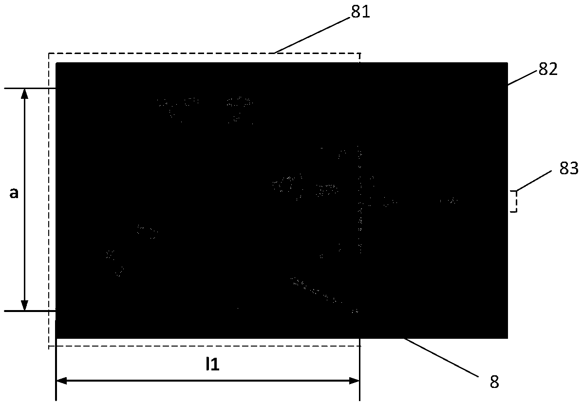
[0032] Embodiment 1. In this embodiment, the distance between the center point of the rectangular groove 9 and the midpoint of a pair of short sides of the third dielectric substrate 3 is s0 = 2 mm.
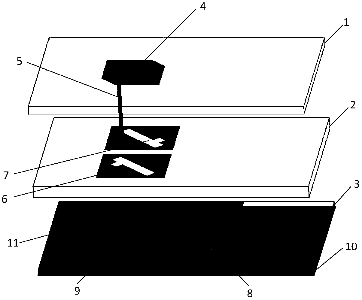
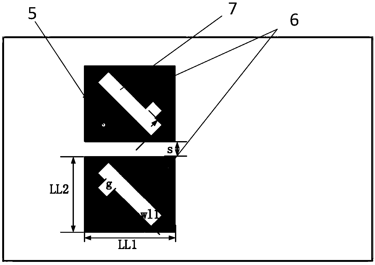
[0033] refer to figure 1 , a dual-frequency circularly polarized antenna based on a substrate-integrated waveguide, comprising a first dielectric substrate 1, and a stacked structure composed of a second dielectric substrate 2 and a third dielectric substrate 3 arranged up and down, the first dielectric substrate 1. Fixed above the laminated structure, the three dielectric substrates from top to bottom are rectangular plates with the same size and thickness of 0.8mm, 1.2mm and 0.575mm respectively. The length is 28mm and the width is 17mm. These dielectric substrates adopt dielectric constant Rogers 5880 material with a loss tangent of 2.2 and a loss tangent of 0.0009.
[0034] The upper surface of the third dielectric substrate 3 is printed with a first metal layer 8, and the l...
Embodiment 2
[0041] Embodiment 2, this embodiment has the same structure as Embodiment 1, only the following parameters have been adjusted:
[0042] The distance between the central point of the rectangular groove 9 and the midpoint of a pair of short sides of the third dielectric substrate 3 is s0 = 1.5 mm.
Embodiment 3
[0043] Embodiment 3, the structure of this embodiment is the same as that of Embodiment 1, only the following parameters have been adjusted:
[0044] The distance between the center point of the rectangular groove 9 and the line connecting the midpoints of a pair of short sides of the third dielectric substrate 3 is s0 = 2.5 mm.
[0045] Effect of the present invention can be further explained in conjunction with simulation result:
[0046] 1. Simulation content
[0047] 1.1 Utilize commercial simulation software HFSS_15.0 to simulate the reflection coefficient in the embodiment of the present invention 1, the result is as follows Figure 5 shown.
[0048] 1.2 Utilize the commercial simulation software HFSS_15.0 to carry out simulation calculation to the axial ratio in embodiment 1 of the present invention, the result is as follows Figure 6 shown.
[0049] 1.3 Utilize the commercial simulation software HFSS_15.0 to simulate the radiation pattern of the xoz plane in Embodi...
PUM
 Abstract
Description
Claims
Application Information
 - Generate Ideas
- Intellectual Property
- Life Sciences
- Materials
- Tech Scout
- Unparalleled Data Quality
- Higher Quality Content
- 60% Fewer Hallucinations
Browse by: Latest US Patents, China's latest patents, Technical Efficacy Thesaurus, Application Domain, Technology Topic, Popular Technical Reports.
© 2025 PatSnap. All rights reserved.Legal|Privacy policy|Modern Slavery Act Transparency Statement|Sitemap|About US| Contact US: help@patsnap.com


