Temperature compensation method for wireless sensor network dip fulcrum

A technology of wireless sensor network and inclination fulcrum, applied in the direction of measuring inclination, signal transmission system, measuring device, etc., can solve the problems of reduced monitoring accuracy, temperature drift error, high cost, etc., to save cost, improve effect, and improve efficiency Effect

Active Publication Date: 2019-01-15
TONGJI UNIV
View PDF5 Cites 2 Cited by
  • Summary
  • Abstract
  • Description
  • Claims
  • Application Information

AI Technical Summary

Problems solved by technology

The performance of electronic components such as silicon capacitive MEMS inclination sensors integrated inside the wireless sensor network inclination fulcrum is sensitive to changes in ambient temperature, resulting in temperature drift errors in the inclination monitoring value of the wireless sensor network inclination fulcrum when the ambient temperature changes. The monitoring accuracy is significantly reduced, and it will not be able to meet the accuracy requirements of the monitoring project
Therefore, it is necessary to perform temperature compensation on the inclination fulcrum of the wireless sensor network. At the same time, it is often necessary to install a large number of inclination fulcrums of the wireless sensor network in a monitoring project. The traditional temperature compensation method based on the temperature chamber test has low efficiency. , high cost, cumbersome test process and other shortcomings, it is difficult to meet the needs, and the environment created by using the temperature test chamber is different from the environment under actual application conditions, it is difficult to guarantee the temperature compensation effect

Method used


Image

  • Temperature compensation method for wireless sensor network dip fulcrum
  • Temperature compensation method for wireless sensor network dip fulcrum
  • Temperature compensation method for wireless sensor network dip fulcrum

Examples


Embodiment

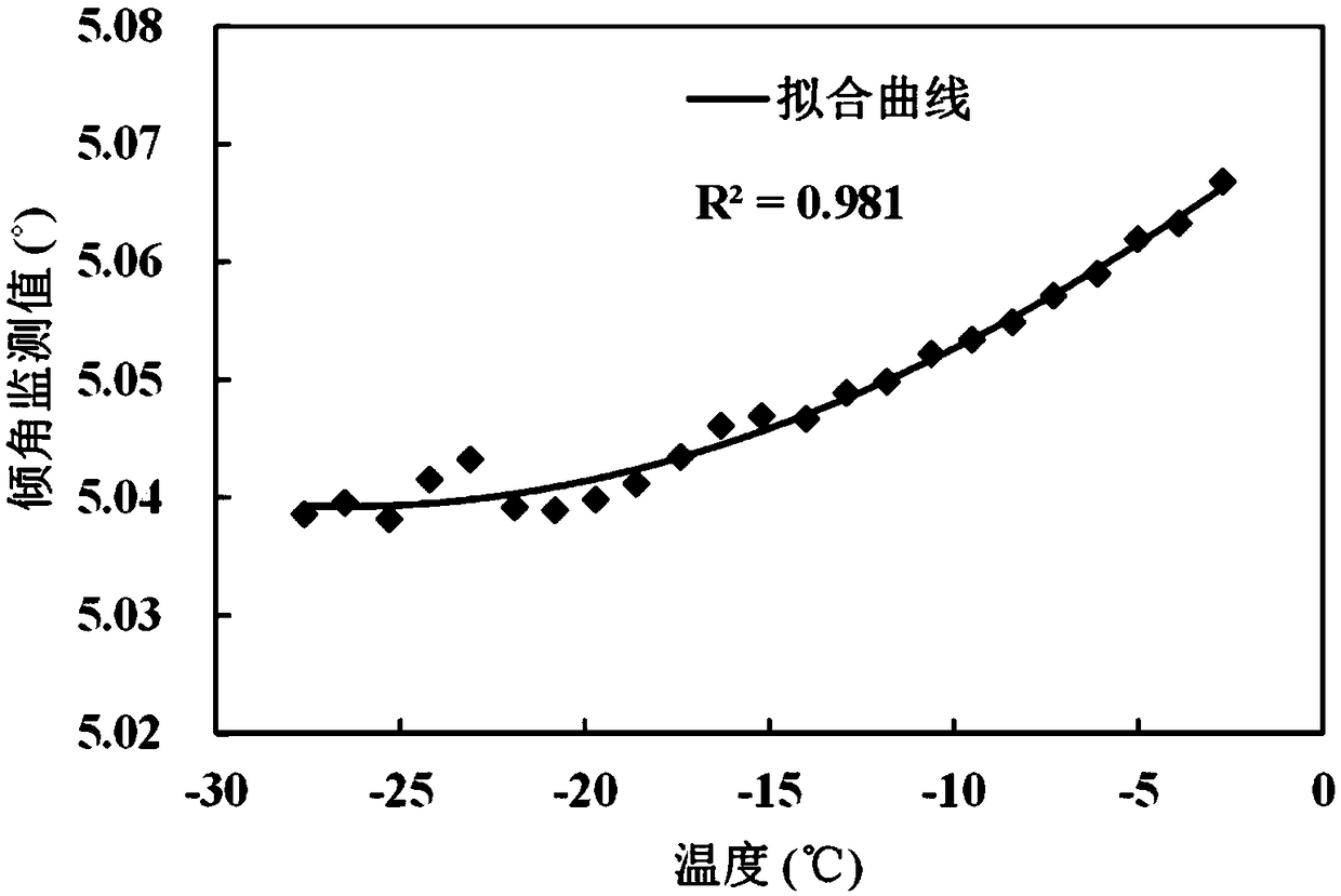
[0048] (1) The inclination fulcrum of the wireless sensor network collects inclination angle and temperature data (such as figure 2 shown) is used to draw the inclination-temperature curve. At each temperature point, the inclination monitoring value satisfies the condition of a fluctuation range of 0.02°, so this period of time can be considered as the stable period of the structure.

[0049] (2) The calibration temperature of the inclination fulcrum is 25°C (it is considered that the temperature drift is zero at this temperature), however figure 2 The range of temperature changes in does not include the calibration temperature. Therefore, firstly, the inclination output value of the inclination fulcrum at 25°C is predicted based on the inclination monitoring data in the stable period. By calculating the average value of the inclination monitoring value of the inclination fulcrum at the same temperature and its fitting curve with the third-order polynomial fitting curve of ...


PUM


Abstract

The invention relates to a temperature compensation method for a wireless sensor network dip fulcrum. The temperature compensation method comprises the following steps that (1) angel values and temperature values of a to-be-detected structure object within the monitoring cycle are collected through the wireless sensor network dip fulcrum; (2) the structure stability period, namely the time periodduring which a structure does not generate inclination and deformation, is determined according to the angel values within the monitoring cycle; (3) a temperature compensation model of the wireless sensor network dip fulcrum is established, and a temperature compensation coefficient is calculated; and (4) according to the temperature compensation model after obtaining the temperature compensationcoefficient, the collected angle values of the wireless sensor network dip fulcrum are automatically compensated. Compared with the prior art, the temperature compensation method has the advantages that temperature testing is not needed, automatic compensation is conducted, the compensation efficiency is improved, and a field application environment is fit.

Description

technical field [0001] The invention relates to the field of monitoring the inclination state of civil engineering structures, in particular to a temperature compensation method for inclination fulcrums of a wireless sensor network. Background technique [0002] Because of its advantages of convenient installation, automatic monitoring, and wireless transmission of monitoring data, wireless sensor network inclination fulcrum is widely used in monitoring the inclination state of civil engineering structures. The performance of electronic components such as silicon capacitive MEMS inclination sensors integrated inside the wireless sensor network inclination fulcrum is sensitive to changes in ambient temperature, resulting in temperature drift errors in the inclination monitoring value of the wireless sensor network inclination fulcrum when the ambient temperature changes. Its monitoring accuracy is significantly reduced, and it will not be able to meet the accuracy requirement...

Claims


Application Information

Patent Timeline
Patent Type & Authority Applications(China)
IPC IPC(8): G01C9/02G08C17/02
CPCG01C9/02G08C17/02
Inventor 黄宏伟杜斐张东明施静康程涛
Owner TONGJI UNIV
Why Eureka
Try Eureka