
Tidal energy generating device

A power generation device and tidal energy technology, which is applied in the field of new energy power generation, can solve the problems of large engineering volume, large construction funds, and low energy conversion efficiency, and achieve the effect of small engineering volume, simple structure, and convenient installation

Active Publication Date: 2019-01-15
威海众海智能科技有限公司
View PDF16 Cites 4 Cited by
  • Summary
  • Abstract
  • Description
  • Claims
  • Application Information

AI Technical Summary

Problems solved by technology

[0002] Tidal energy is the energy obtained from the day and night fluctuations of the sea surface. It is related to the gravitational force of celestial bodies. The attraction and thermal energy of the earth-moon-sun system are the sources of tidal energy. Tidal energy includes two modes of movement: tide and current. The energy contained in the tide contains huge energy in the ups and downs. This energy is eternal and non-polluting energy. The tidal generators that exist today use the tidal drop to generate electricity, usually requiring a drop of more than ten meters, and There are great requirements on the installation location of the power generation device, the energy conversion efficiency is low, and the project volume is huge, which requires a lot of construction funds. Therefore, we propose a tidal energy power generation device, which is easy to install and has high energy conversion efficiency. , suitable for use when the demand for power generation is small

Method used


Image

  • Tidal energy generating device
  • Tidal energy generating device
  • Tidal energy generating device

Examples


no. 1 approach

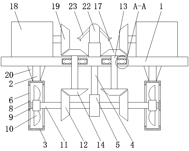
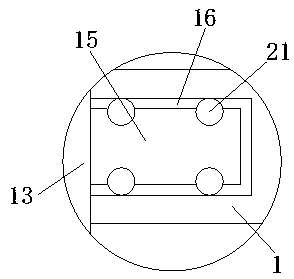
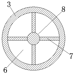
[0017] First implementation: see Figure 1-3 , a tidal energy power generation device, comprising a mounting plate 1, both sides of the bottom of the mounting plate 1 are fixedly connected with a water wheel housing 3 through a first connecting rod 2, the bottom of the mounting plate 1 corresponds to the left and right sides of the first connecting rod 2 Both sides are fixedly connected with a reinforcing rib 20, and the side of the reinforcing rib 20 close to the first connecting rod 2 is fixedly connected with the first connecting rod 2, and the midpoint of the bottom of the mounting plate 1 is fixedly connected with a bearing 5 through the second connecting rod 4, The inner wall on both sides of the water wheel housing 3 is provided with a water outlet 6, and the inner wall of the outer water outlet 6 is fixedly connected with a fixed piece 8 through four connecting ribs 7, and the side of the fixed piece 8 close to the bearing 5 passes through the connecting shaft 9 A wate...

no. 2 approach

[0019] The second embodiment: a tidal energy power generation device, including a mounting plate 1, both sides of the bottom of the mounting plate 1 are fixedly connected with a water wheel housing 3 through a first connecting rod 2, and the middle of the bottom of the mounting plate 1 The point is fixedly connected with a bearing 5 through the second connecting rod 4, the bottom of the bearing 5 is provided with a floating ball, and the inner wall of the water wheel housing 3 on both sides is provided with a water outlet 6, which is located on the inner wall of the outer water outlet 6. The four connecting ribs 7 are fixedly connected with a fixed piece 8, the side of the fixed piece 8 close to the bearing 5 is movably connected with a water wheel 10 through the connecting shaft 9, and the side of the water wheel 10 on the left side close to the bearing 5 is fixedly connected with a The first rotating shaft 11, the water wheel 10 on the right side near the bearing 5 is fixedly...


PUM


Abstract

The invention discloses a tidal energy generating device. The tidal energy generating device comprises a mounting plate. Water shell shells are fixedly connected to two sides of the bottom of the mounting plate by first connecting rods. A bearing is fixedly connected to the center of the bottom of the mounting plate by a second connecting rod. Water openings are formed in the inner walls of two sides of the water shells. Fixing pieces are fixedly connected to the inner walls of the water openings located on the outer sides by four connecting ribs. Water wheels are movably connected to the sides, close to the bearing, of the fixing pieces by connecting shafts. First rotating shafts are fixedly connected to the sides, close to the bearing, of the water wheels. The ends, close to the bearing,of the first rotating shafts sequentially penetrate through the water wheel shells and the bearing, and extend into the bearing. The structure is simple. High requirements are not needed for the mounting positions. Energy transferring efficiency is reduced by gear transmission. The work amount is little. Excessive construction cost is not required. Application in condition with less power generating demand can be achieved.

Description

technical field [0001] The model relates to the technical field of new energy power generation, in particular to a tidal energy power generation device. Background technique [0002] Tidal energy is the energy obtained from the day and night fluctuations of the sea surface. It is related to the gravitational force of celestial bodies. The attraction and thermal energy of the earth-moon-sun system are the sources of tidal energy. Tidal energy includes two modes of movement: tide and current The energy contained in the tide contains huge energy in the ups and downs. This energy is eternal and non-polluting energy. The tidal generators that exist today use the tidal drop to generate electricity, usually requiring a drop of more than ten meters, and There are great requirements for the installation location of the power generation device, the energy conversion efficiency is low, and the project volume is huge, which requires a lot of construction funds. Therefore, we propose a t...

Claims


Application Information

Patent Timeline
Patent Type & Authority Applications(China)
IPC IPC(8): F03B13/26F03B11/00F03D9/00F03D9/25F03D80/70H02K7/18
CPCF03B11/00F03B13/264F03D9/008F03D9/25F03D80/70H02K7/1823Y02E10/20Y02E10/30Y02E10/72Y02P70/50
Inventor 李超杰
Owner 威海众海智能科技有限公司
Learn More