
Engine oil filter strainer assembly for engine and engine

An oil filter and engine technology, which is applied in the field of vehicle lubrication systems, can solve the problems of smaller oil storage space in the oil pan, decreased stability, and the lubrication system cannot be lubricated normally, and achieves the effect of increasing adaptability and reducing cylinder pulling.

Pending Publication Date: 2019-01-15
WEICHAI POWER CO LTD
View PDF7 Cites 1 Cited by
  • Summary
  • Abstract
  • Description
  • Claims
  • Application Information

AI Technical Summary

Problems solved by technology

[0004] In order to allow the transmission shaft to pass through the bottom of the oil pan, it is easy to think of ways to increase the minimum ground clearance and raise the oil pan, but once the minimum ground clearance is increased, the stability of the vehicle movement It will drop accordingly, and, after increasing the minimum ground clearance, the oil storage space in the oil pan will be relatively smaller
And because the lubricating device among the prior art generally only is provided with a filter filter, and the filter filter is an integral bent part, and its oil suction port is fixed, under different states of vehicle operation, such as acceleration / starting, deceleration / Braking, uphill, downhill, etc., the lubricating oil in the oil pan will tilt in a certain direction, and the oil suction port of the filter located in the oil pan cannot always be located in the liquid level of the oil in the oil pan. Below the surface, so that when the oil suction port of the filter is above the liquid surface, the lubrication system cannot be lubricated normally

Method used


Image

  • Engine oil filter strainer assembly for engine and engine
  • Engine oil filter strainer assembly for engine and engine
  • Engine oil filter strainer assembly for engine and engine

Examples


Embodiment Construction

[0026] Exemplary embodiments of the present disclosure will be described in more detail below with reference to the accompanying drawings. Although exemplary embodiments of the present disclosure are shown in the drawings, it should be understood that the present disclosure may be embodied in various forms and should not be limited by the embodiments set forth herein. Rather, these embodiments are provided for more thorough understanding of the present disclosure and to fully convey the scope of the present disclosure to those skilled in the art.

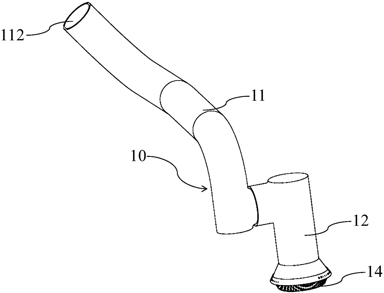
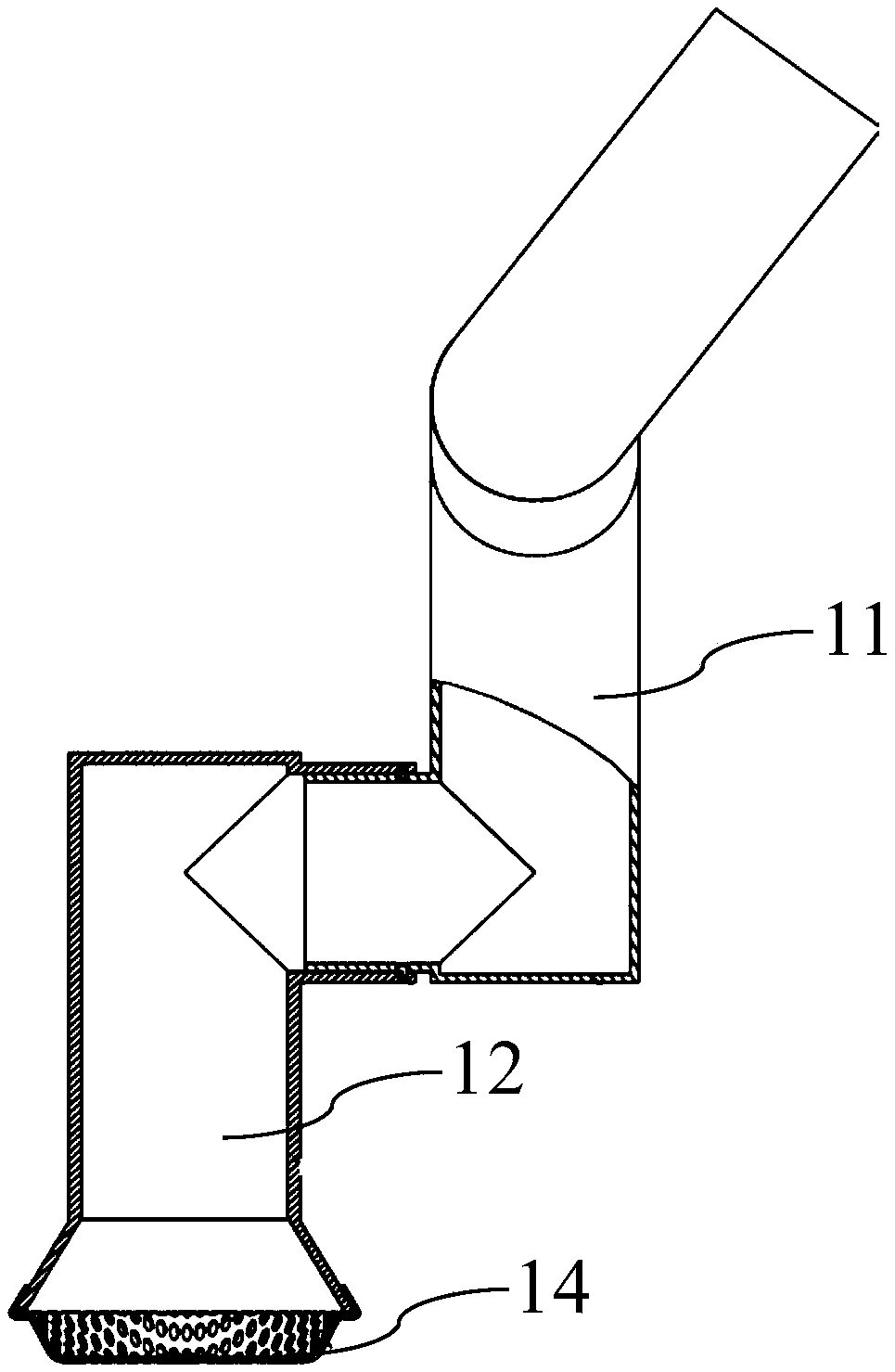
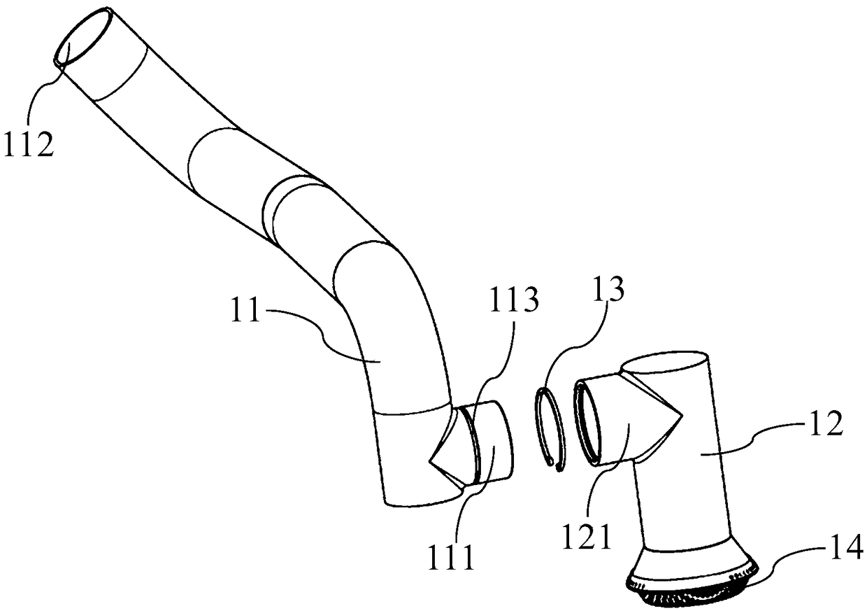
[0027] figure 1 It is a schematic diagram of the overall structure of the embodiment of the present invention. figure 2 for figure 1 The partial cross-sectional structure schematic diagram of the embodiment. image 3 for figure 1 Schematic diagram of the decomposition structure of the embodiment. The oil collector assembly 10 for an engine in this embodiment includes a first pipe 11 and a second pipe 12 . Wherein, the top of ...


PUM


Abstract

The invention belongs to the technical field of vehicle lubrication systems, and particularly relates to an engine oil filter strainer assembly for an engine and the engine. The engine oil filter strainer assembly for the engine comprises a first pipe fitting and a second pipe fitting. An oil outlet is formed in the top end of the first pipe fitting. The first pipe fitting communicates with the engine. A first extending end used for being connected with the second pipe fitting is arranged at the outer lateral face in the radial direction of the bottom end of the first pipe fitting. An oil sucking opening is formed in the bottom end of the second pipe fitting, and the oil sucking opening faces the liquid level direction in the oil bottom shell. A second extending end used for being connected with the first pipe fitting is arranged at the top end of the second pipe fitting. The first extending end and the second extending end communicate in a pivot-rotating mode. Through the engine oil filter strainer assembly for the engine and the engine, it can be ensured that the engine can suck the engine oil, adaptation to different road conditions of the engine is improved, and the risks of cylinder scoring and tile melting caused by the engine being unable to absorb the engine oil are reduced.

Description

technical field [0001] The invention belongs to the technical field of vehicle lubricating systems, and in particular relates to an engine oil collector assembly and an engine. Background technique [0002] There are a large number of kinematic pairs among the internal moving parts of the automobile engine, and the relative motion between these kinematic pairs is very violent. It is necessary for the vehicle lubricating device to deliver lubricating oil to each kinematic pair so that there is enough oil between each kinematic pair. Lubricate and cool. [0003] Existing cars generally adopt the form of four-wheel drive. The so-called four-wheel drive means that the front and rear wheels of the car have power. driving ability. When four-wheel drive is adopted, a transmission shaft is designed between the front wheel and the rear wheel of the vehicle, and the transmission shaft needs to pass through the lower part of the oil pan of the engine. When the oil sump of the engine...

Claims


Application Information

Patent Timeline
Patent Type & Authority Applications(China)
IPC IPC(8): F01M11/00F01M11/03
CPCF01M11/00F01M11/03
Inventor 隋鹏超魏志友于超
Owner WEICHAI POWER CO LTD
Learn More