Washing machine inner cylinder and washing machine
A technology of a washing machine and an inner cylinder, which is applied in the field of washing machines, and can solve the problems of poor cleaning effect and easy accumulation of dirt in the concave part of the washing machine that is not arranged on the concave part of the outer wall of the inner cylinder, and achieves the effect of simple structure, low cost and good cleaning effect
- Summary
- Abstract
- Description
- Claims
- Application Information
AI Technical Summary
Problems solved by technology
Method used
Image
Examples
Embodiment 1
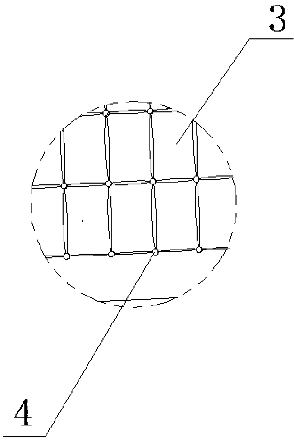
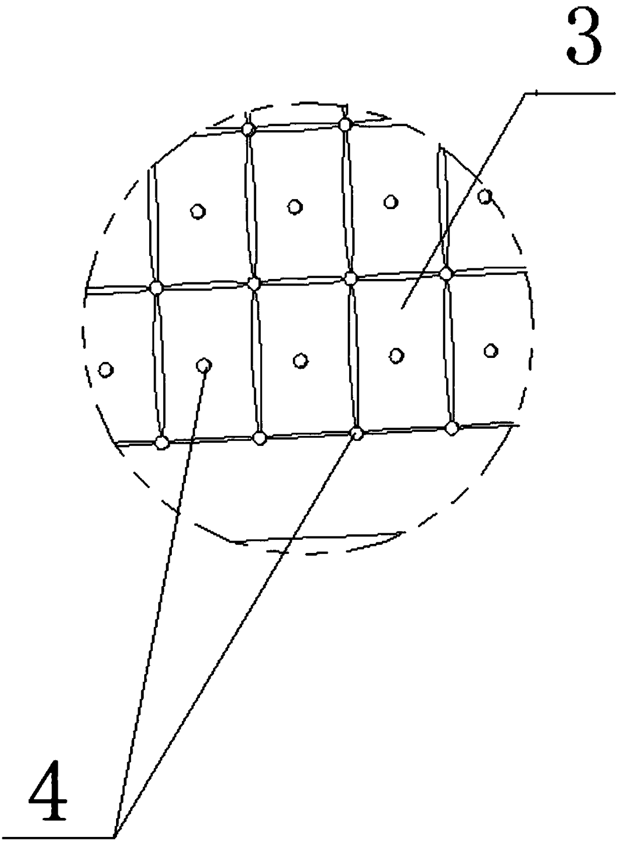
[0051] see Figure 1-Figure 4 As shown, this embodiment provides an inner cylinder of a washing machine, the cylinder wall of which is provided with concave-convex moldings 3 having concave and convex parts, and a dehydration hole 4 is provided on the cylinder wall of the inner cylinder, and the dehydration hole 4 corresponds to the inner cylinder. The concave part of the cylinder outer wall 2 is provided.
[0052] In the above scheme, considering that the concave portion of the inner cylinder outer wall 2 is a place where dirt is easy to accumulate, a water hole is opened at this place, which is beneficial for washing water to enter the concave portion through the dehydration hole 4, and the concave portion is washed and cleaned, thereby This prevents the recess from becoming a dead corner for cleaning the inner tub of the washing machine.
[0053] Preferably, the concave-convex profile 3 is formed by a plurality of protrusions facing the inside of the inner cylinder, and ea...
Embodiment 2
[0068] This embodiment is described on the basis of Embodiment 1: the profiling 3 on the inner cylinder of the washing machine is a plurality of closely distributed quadrilateral profiling 3 formed by stamping from the outer side of the inner cylinder to the inner side, and the quadrilateral profiling 3 consists of a planar structure The bottom surface of the bottom surface and the transition surface smoothly transitioned from the bottom surface to the inner cylinder outer wall 2, the transition surface is a curved surface, wherein the dehydration holes 4 are partly arranged on the bottom surface of the quadrilateral profiling 3, and partly arranged on the transition surface.
[0069] Alternatively, the profile 3 is a bar-shaped groove structure protruding toward the inside of the inner cylinder, and the dehydration holes 4 are evenly distributed on the bottom of the groove, or the dehydration holes 4 are partially arranged on the bottom of the groove. The groove bottom of the ...
Embodiment 3
[0071] This embodiment has been improved on the basis of Embodiment 1, see figure 1 with figure 2 As shown, the concave-convex profile 3 on the inner cylinder is composed of several quadrilateral protrusions facing the outside of the inner cylinder, each protrusion is arranged in rows and columns, and the gaps between the protrusions of adjacent columns and adjacent rows constitute the inner There are several linear recessed passages on the outer wall 2 of the barrel, and the dehydration holes 4 are arranged on the linear recessed passages.
[0072] Preferably, the concave channel formed between the protrusions of two adjacent columns and the concave channel formed between the protrusions of two adjacent rows are perpendicular to each other, see figure 2 As shown, the dehydration holes 4 are arranged at the positions where the channels of the recesses vertically intersect each other.
[0073] In the above scheme, setting the dehydration holes 4 at the positions where the c...
PUM
 Abstract
Description
Claims
Application Information
 - Generate Ideas
- Intellectual Property
- Life Sciences
- Materials
- Tech Scout
- Unparalleled Data Quality
- Higher Quality Content
- 60% Fewer Hallucinations
Browse by: Latest US Patents, China's latest patents, Technical Efficacy Thesaurus, Application Domain, Technology Topic, Popular Technical Reports.
© 2025 PatSnap. All rights reserved.Legal|Privacy policy|Modern Slavery Act Transparency Statement|Sitemap|About US| Contact US: help@patsnap.com


