
Washing machine

A washing machine and washing tub technology, applied in the field of washing machines, can solve the problems of increased inner tub vibration, large volume, damage to motors, etc., and achieve the effects of reducing usage, improving utilization rate, and long service life

Inactive Publication Date: 2019-01-15
QINGDAO HAIER WASHING MASCH CO LTD +1
View PDF6 Cites 6 Cited by
  • Summary
  • Abstract
  • Description
  • Claims
  • Application Information

AI Technical Summary

Problems solved by technology

[0002] Existing pulsator washing machines generally consist of a washing tub, an outer tub, a vibration-damping component and a power system. During washing and dehydration, the washing tub rotates relative to the outer tub so that the clothes interact with the washing water to achieve the effect of washing or dehydrating the clothes. Purpose, wherein, the outer tub is used as a water bucket, and does not come into contact with the clothes during the laundry process, and the outer tub is installed outside the washing tub to provide support for the washing tub. The outer tub of the existing washing machine is larger than the washing tub, As a result, there is a large amount of washing water between the inner and outer tubs, which cannot be fully utilized. This setting is not conducive to water saving, but also causes the overall volume of the washing machine to be too large
The Chinese invention patent with the patent number of 99230455.5 discloses a single-tub water-saving washing machine. A water collecting device is provided at the mouth of the washing bucket, and the water collecting mouth of the water collecting device is surrounded by the mouth of the washing bucket. The water collecting device located at the mouth of the bucket is connected to several drainage pipes, which are symmetrically arranged from top to bottom along the outer wall of the washing bucket. When drying, the water collecting device collects the centrifugal water flow caused by high-speed rotation and sends it downward. Guide draining, although the patent omits the outer tub, but when the washing machine is dehydrating, the washing water will be concentrated in the water collecting chamber under the action of centrifugal force after entering the water collecting device, and it is difficult to flow downward along the drain pipe, resulting in washing The water concentrates on the upper end of the washing bucket, which makes the upper and lower ends of the washing bucket unbalanced, especially when there is a lot of residual water in the washing bucket, most of the washing water is concentrated in the water collecting chamber and is not discharged, which increases the overall center of gravity of the inner bucket and increases the vibration of the inner bucket. Increases the working load of the dehydration motor, which is easy to damage the motor

Method used


Image

  • Washing machine
  • Washing machine
  • Washing machine

Examples


Embodiment 1

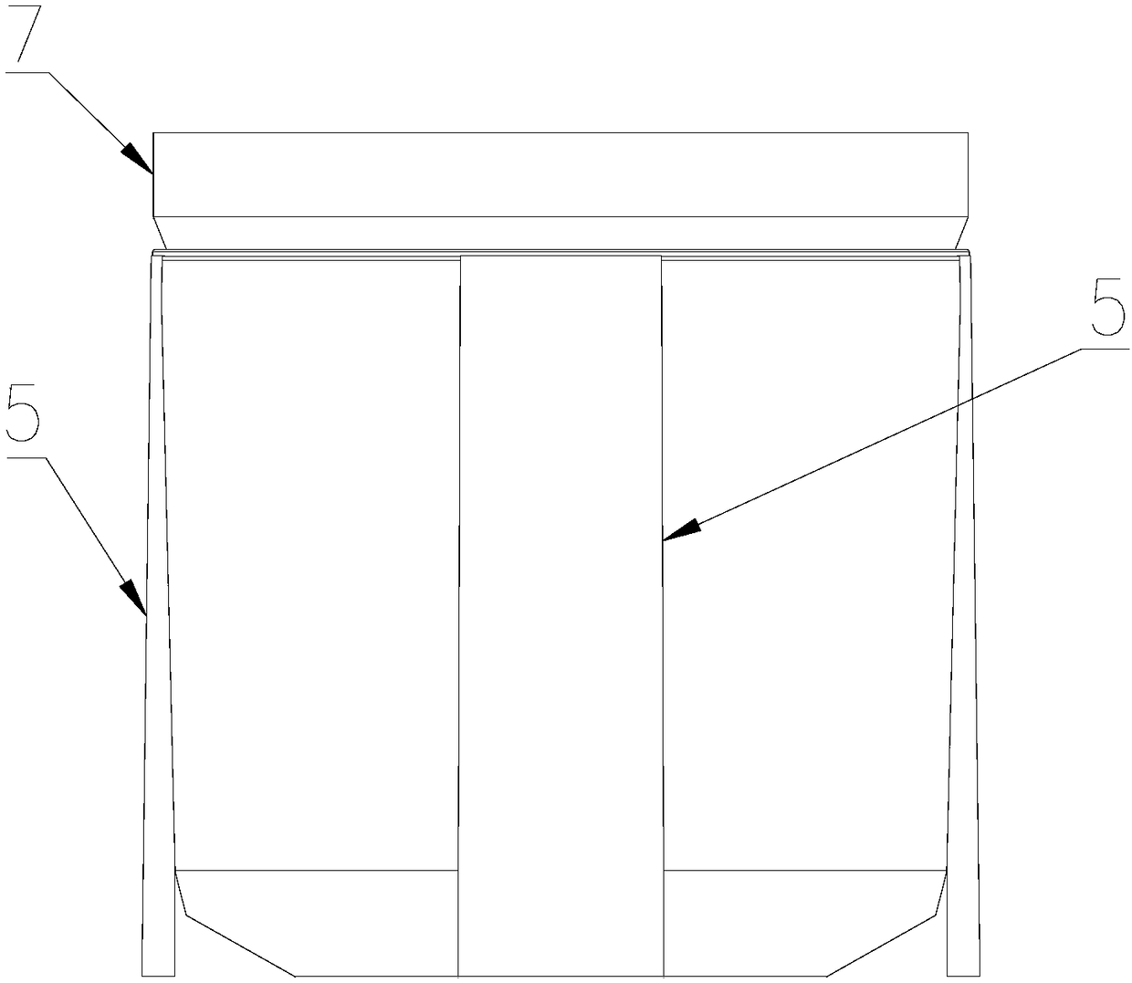
[0029] Such as Figure 1 to Figure 4 As shown, a washing machine includes a box body 1, a washing tub 2 for accommodating laundry to be washed, a power unit 3 for driving the washing tub 2 to rotate, a mounting plate 4 installed at the bottom of the washing tub 2, and a connecting mounting plate 4 Vibration-absorbing parts with box 1. The washing bucket 2 is rotatably arranged in the box body 1. The washing bucket 2 is located on the mounting plate 4 and can rotate relative to the mounting plate 4. The washing bucket 2 is used as a bucket for containing washing water, and the mounting plate 4 is used for The washing bucket 2 is supported, and the mounting plate 4 is movably connected with the box body 1 through the damping component. When washing or dehydrating, the washing bucket 2 and the mounting plate 4 will vibrate, and the vibration will be absorbed after being transmitted to the damping component.

[0030] A water retaining ring 13 is provided on the mounting plate 4, ...

Embodiment 2

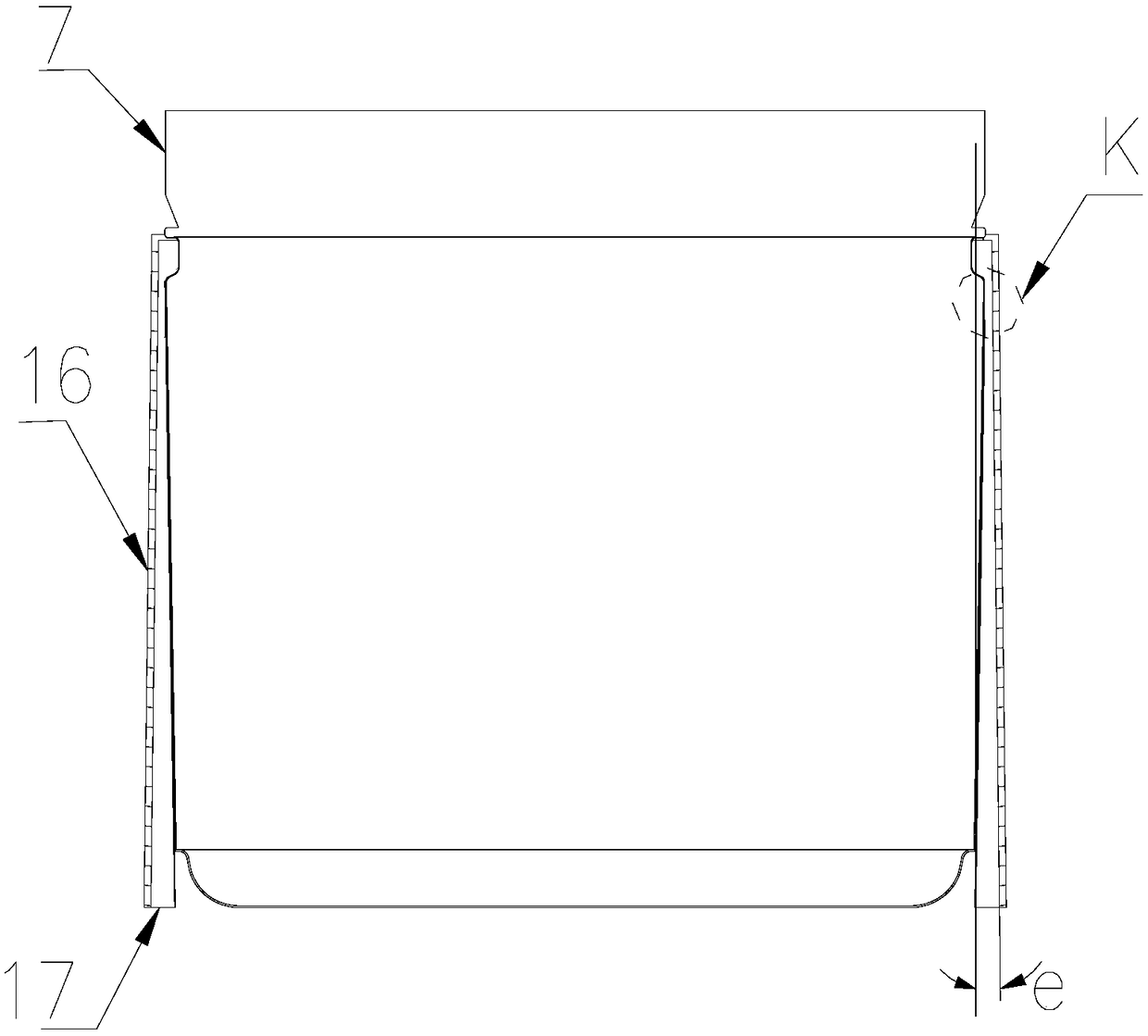
[0044] Such as Figure 5 to Figure 8 As shown, the difference between this embodiment and Embodiment 1 is that the upper end of the washing bucket 2 is also provided with a water collection ring 11, and the inner side of the water collection ring 11 is provided with a dehydration hole 8 communicating with the washing bucket 2. The upper end of the channel 5 communicates with the water collecting ring 11 , and the lower end communicates with the inner drain provided at the bottom of the washing tub 2 .

[0045] The inner diameter of the washing bucket 2 gradually increases from bottom to top. When the washing bucket 2 rotates at a high speed, the washing water in the washing bucket 2 will climb upwards along the wall of the washing bucket under the action of centrifugal force, and after rising to a certain height, Enter in the water collection ring 11 from the dewatering hole 8 of the water collection ring 11, the volume of the water collection ring 11 is relatively small, and ...


PUM


Abstract

The invention relates to a washing machine. The washing machine includes a casing, a washing tub used for storing the water and a mounting board which is mounted at a lower portion of the washing tuband is used for supporting the washing tub, wherein the mounting board is connected with the casing through a damping part, the washing tub is rotatably arranged relative to the mounting board, an outer side of the washing tub is provided with multiple drainage channels, an upper end of the drainage channels is communicated with an inner portion of the washing tub, a lower end of the drainage channels extends to the bottom of the washing tub along the tub wall of the washing tub, the lower end is communicated with a drainage port of the washing machine, and an inner wall surface of the drainage channels on the side opposite to the washing tub gradually deviates away the axis of the washing tub from up to down at a deviation angle of 0-10 DEG relative to the axis of the washing tub. The washing machine is advantaged in that an outer tub structure is omitted, capacity expansion of the washing machine is achieved, the outer side of the washing tub is provided with multiple drainage channels, the washing water is prevented from being concentrated on an upper end of the washing tub, operation noise is low, and service life is long.

Description

technical field [0001] The invention relates to laundry equipment, in particular to a washing machine. Background technique [0002] Existing pulsator washing machines generally consist of a washing tub, an outer tub, a vibration-damping component and a power system. During washing and dehydration, the washing tub rotates relative to the outer tub so that the clothes interact with the washing water to achieve the effect of washing or dehydrating the clothes. Purpose, wherein, the outer tub is used as a water bucket, and does not come into contact with the clothes during the laundry process, and the outer tub is installed outside the washing tub to provide support for the washing tub. The outer tub of the existing washing machine is larger than the washing tub, As a result, there is a large amount of washing water stored between the inner and outer tubs, which cannot be fully utilized. This arrangement is not only unfavorable for water saving, but also causes the overall volu...

Claims


Application Information

Patent Timeline
Patent Type & Authority Applications(China)
IPC IPC(8): D06F23/04D06F37/24D06F37/30D06F39/08
CPCD06F23/04D06F37/24D06F37/30D06F39/083
Inventor 吴迪郝兴慧李以民劳春峰吕艳芬许升吕佩师
Owner QINGDAO HAIER WASHING MASCH CO LTD
Learn More