
Power distribution switchgear auxiliary operation robot

An auxiliary operation and robot technology, applied in the direction of manipulator, program control manipulator, chuck, etc., can solve the problems of low efficiency of power distribution switchgear, poor activity performance of operating equipment, reduced equipment efficiency, etc., to improve the flexibility of movement and the range of movement. , compact structure, easy to use effect

Pending Publication Date: 2019-01-15
广东省机器人创新中心有限公司
View PDF0 Cites 7 Cited by
  • Summary
  • Abstract
  • Description
  • Claims
  • Application Information

AI Technical Summary

Problems solved by technology

[0003] Usually the power distribution switchgear is operated manually, but because the power distribution switchgear is in a high-voltage state when it is working, there is a greater risk in manual operation. In the prior art, the power distribution switchgear is also operated by operating equipment, but the existing operation The activity performance of the equipment is poor, and the efficiency is low when operating complex power distribution switch cabinets. Multiple movements are required to operate the switches of the power distribution switch cabinets. In addition, the knives used to operate the power distribution switch cabinets also need The equipment needs to be replaced before it enters the switch cabinet. Every time the tool is replaced, the equipment needs to be removed and replaced manually, which reduces the efficiency of equipment operation.

Method used


Image

  • Power distribution switchgear auxiliary operation robot
  • Power distribution switchgear auxiliary operation robot
  • Power distribution switchgear auxiliary operation robot

Examples


Embodiment Construction

[0031] The specific embodiments of the present invention will be described in further detail below in conjunction with the drawings and embodiments. The following examples are used to illustrate the present invention, but not to limit the scope of the present invention.

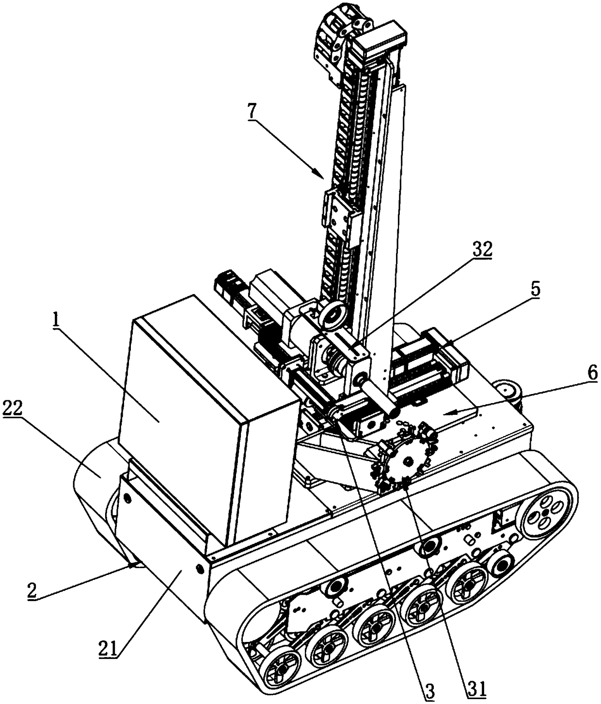
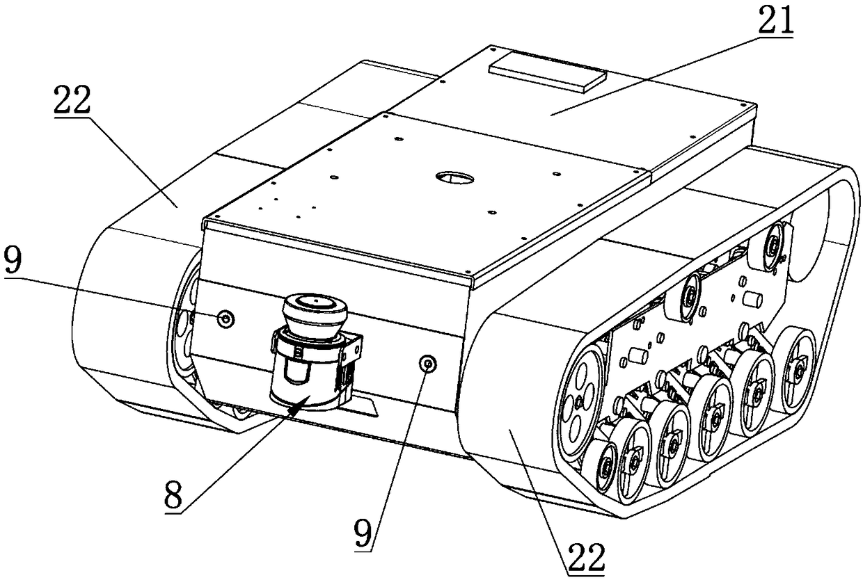
[0032] reference Figure 1~6 , This embodiment provides a power distribution switchgear auxiliary operation robot, including a control device 1 and a moving device 2, an operating device 3, an X-axis moving device 4, a Y-axis moving device 5, and a rotating seat electrically connected to the control device 1. 6 and the Z-axis moving device 7. The Y-axis moving device 5 is installed on the moving device 2 through the rotating base 6. The Z-axis moving device 7 is connected to the Y-axis moving device 5 to move along the Y-axis direction; the X-axis moving device 4 is connected Move the device 7 on the Z axis to move along the Z axis;

[0033] Operating device 3, including tool change assembly 31 and operating ass...


PUM


Abstract

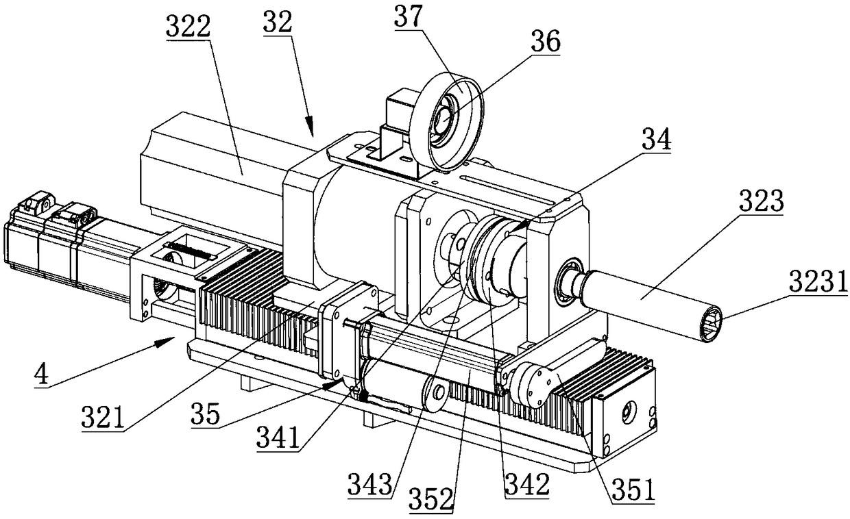
The present invention relates to the technical field of power distribution switchgear operation and more particularly to a power distribution switchgear auxiliary operation robot. The robot comprisesa control device and also comprises a moving device, an operation device, an X-axis moving device, a Y-axis moving device, a rotation seat and a Z-axis moving device electrically connected to the control device. The operation device comprises a tool change assembly and an operation assembly, and the operation assembly comprises an X-axis moving seat, a clamp rotating unit and an operating clamp. The operating clamp is connected to a power output end of the clamp rotating unit, and the clamp rotating unit is connected to the X-axis moving device through the X-axis moving base to move along an X-axis direction. The tool change assembly includes a tool change driving unit, a support frame and a tool change disc. A first end of the support frame is fixed to the moving device, the tool change driving unit and the tool change disc are installed on a second end of the support frame, and the tool change driving unit is connected to the tool change disc to rotate the tool change disc for the operating clamp to change a tool. According to the power distribution switchgear auxiliary operation robot, the efficiency of the operation of a power distribution switchgear is effectively improved.

Description

Technical field [0001] The present invention relates to the technical field of power distribution switch cabinet operation, in particular to a power distribution switch cabinet auxiliary operation robot. Background technique [0002] Substation is to assemble some equipment to cut off or connect, change or adjust the voltage. In the power system, the substation is the gathering point of power transmission and distribution. The power distribution switchgear is an indispensable power distribution switchgear in the substation, which is used for the transmission and control of electric energy. Generally, the operation of the main switchgear equipped in the distribution switch cabinet uses electrical operation buttons to realize the switch action. For example, the cabinet surface of a 10kV switch cabinet has switch button components that operate the circuit breaker to open and close. [0003] Usually the power distribution switchgear is operated manually, but because the power distribu...

Claims


Application Information

Patent Timeline
IPC IPC(8): B25J5/00B25J9/02B25J15/04
CPCB25J5/005B25J9/02B25J15/04B25J15/0491
Inventor 华栋崔佩仪崔顺炬袁文飞林清霖
Owner 广东省机器人创新中心有限公司
Learn More