
artificial valve prosthesis

An artificial valve and valve technology, applied in the field of medical devices, can solve the problems of valve annulus tissue compression, artificial valve prosthesis not well fitting the anatomical structure of the mitral valve, etc., and achieve good leak-proof effect

Active Publication Date: 2020-06-12
NINGBO JENSCARE BIOTECHNOLOGY CO LTD
View PDF14 Cites 1 Cited by
  • Summary
  • Abstract
  • Description
  • Claims
  • Application Information

AI Technical Summary

Problems solved by technology

The present invention solves the problem of semicircular leakage caused by the artificial valve prosthesis in the prior art that cannot fit well to the anatomical structure of the mitral valve; it also solves the problem of radial expansion of the mitral valve annulus due to the need for fixation to the annulus. oppression problem

Method used


Image

  • artificial valve prosthesis
  • artificial valve prosthesis
  • artificial valve prosthesis

Examples


specific Embodiment 1

[0067] At present, most artificial valve anchoring methods are that the stent radially expands and squeezes the annulus. In order to obtain sufficient radial support, doctors will choose an artificial valve that is larger than the patient's own annulus. Large-sized artificial valves will not only compress the heart tissue and affect the movement of the heart, but also affect the blood flow in the left ventricular outflow tract. Simultaneously because of it can not fit patient's atrium wall and the inhomogeneous physiological structure of self valve ring well, leak-proof effect is also unsatisfactory.

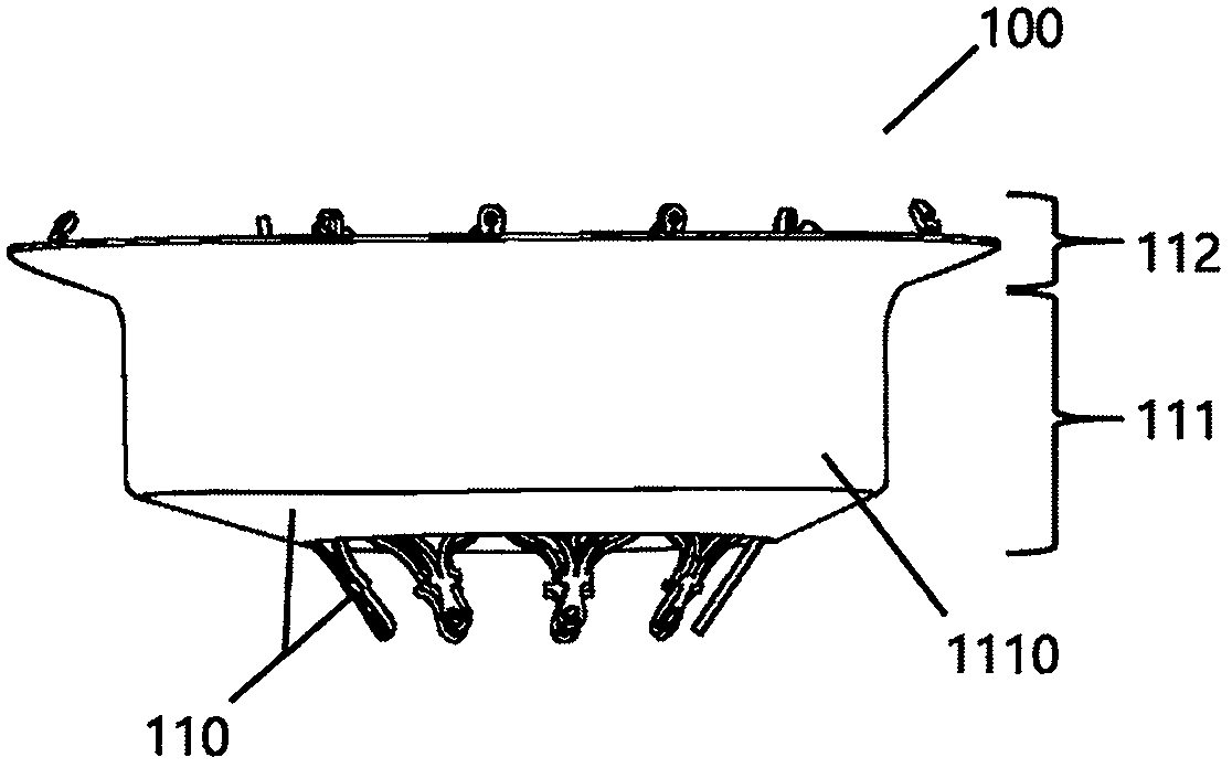
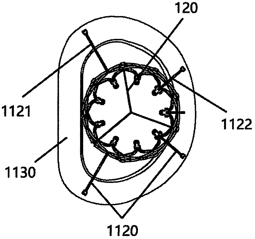
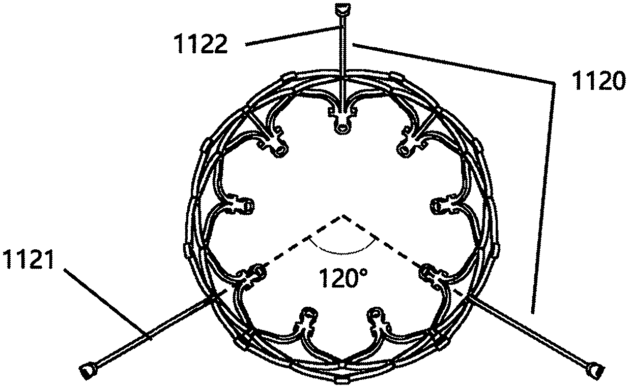
[0068] Therefore, we propose a novel artificial valve prosthesis that can solve the above problems. In one embodiment, as Figure 1a and Figure 1b As shown, an artificial valve prosthesis 100 is used for mitral valve interventional treatment, including a stent 110 and a valve 120, the stent 110 includes a valve sewing segment 111 and an atrium segment 112, and the valve 120 i...

specific Embodiment 2

[0077] In one embodiment, as Figure 11a and Figure 11b As shown, an artificial valve prosthesis 200 is used for mitral valve interventional treatment, including a stent 210 and a valve, and the stent 210 includes a valve sewing segment 211 and an atrium segment 212, and the valve is sewn on the valve On the sewing section 211 , the valve sewing section 211 is connected with the atrium section 212 . The stent is a conical structure, the stent body 213 is a self-expanding structure, and the raw material of the stent body 213 is memory alloy tube. The atrium segment 212 is composed of radial rod-shaped supports 2120. The rod-shaped supports 2120 include two main supports 2121 and two auxiliary supports 2122. One end of the rod-shaped supports 2120 is connected to the The valve sewing segment 211 is fixedly connected as a fixed end, and the other end of the rod-shaped support member 2120 is free as a free end. In a preferred embodiment, the memory alloy tube is a nickel-titan...


PUM


Abstract

A prosthetic valve prosthesis including stents and valves, the stent comprises a valve seam segment and an atrial segment, a valve is fixedly attached to the seam of the valve, a suture segment of that valve is connected with an atrial segment, the atrial segment consists of radial rod-shaped supports, a rod-shaped support include two main supports and at least one auxiliary support, one end of the rod-shaped support is fixedly connected with the valve sewing section as a fixing end. The other end of the rod-shaped support is dissociated as a free end, a flexible skirt is arranged between adjacent rod-shaped supports, and the atrial segment can be adapted into a D-shaped structure when the atrial segment is completely released. The connecting line of the free end of the main support constitutes a straight section of the D-shaped structure, and the free end of the auxiliary support is located on an arc section of the D-shaped structure. On the basis of guaranteeing reliable fixation, the invention not only reduces the influence of valve convection, but also reduces the pressure on heart tissue and the influence on heart motion, and has better leakage prevention effect.

Description

Technical field: [0001] The invention belongs to the field of medical equipment, in particular to an artificial valve prosthesis. [0002] technical background: [0003] The human heart has four chambers and four valves, the mitral valve, tricuspid valve, aortic valve and pulmonary valve. Among them, the mitral valve is located between the left atrium and the left ventricle, and is composed of five parts: leaflets, valve ring, papillary muscles, chordae and junction. The mitral valve acts like a one-way valve. When the heart is diastolic, the mitral valve opens to allow blood to flow from the left atrium into the left ventricle. When the heart is in systole, the mitral valve closes to prevent blood from flowing from the left ventricle of the heart to the left ventricle. Left atrial regurgitation. [0004] According to the latest epidemiological survey data of Western developed countries such as the United States, mitral valve insufficiency (also known as mitral regurgitatio...

Claims


Application Information

Patent Timeline
Patent Type & Authority Patents(China)
IPC IPC(8): A61F2/24
CPCA61F2/2409A61F2/2412A61F2/2418A61F2/2427A61F2210/0014A61F2220/0008A61F2220/0016A61F2250/006A61F2250/0098
Inventor 曹鹏陈志张海云李毅斌
Owner NINGBO JENSCARE BIOTECHNOLOGY CO LTD
Learn More