
High-power permanent magnet motor rotor structure

A permanent magnet motor and rotor structure technology, applied in the direction of magnetic circuit shape/style/structure, magnetic circuit rotating parts, magnetic circuit, etc., to achieve high reliability, reduce moment of inertia, and save the effect of installation tooling

Pending Publication Date: 2019-01-11
SHANGHAI MARINE EQUIP RES INST
View PDF3 Cites 1 Cited by
  • Summary
  • Abstract
  • Description
  • Claims
  • Application Information

AI Technical Summary

Problems solved by technology

[0005] The present invention is to provide a high-power permanent magnet motor rotor structure, the main purpose of which is to solve the technical problem of the permanent magnet rotor magnetic pole fixing method of the permanent magnet motor

Method used


Image

  • High-power permanent magnet motor rotor structure
  • High-power permanent magnet motor rotor structure

Examples


Embodiment Construction

[0021] The present invention will be further described below in conjunction with accompanying drawing.

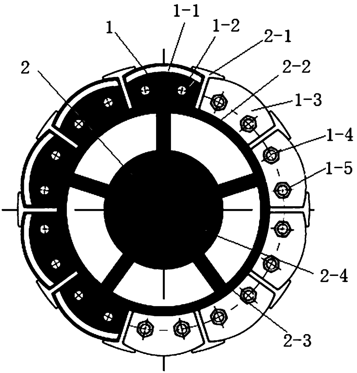
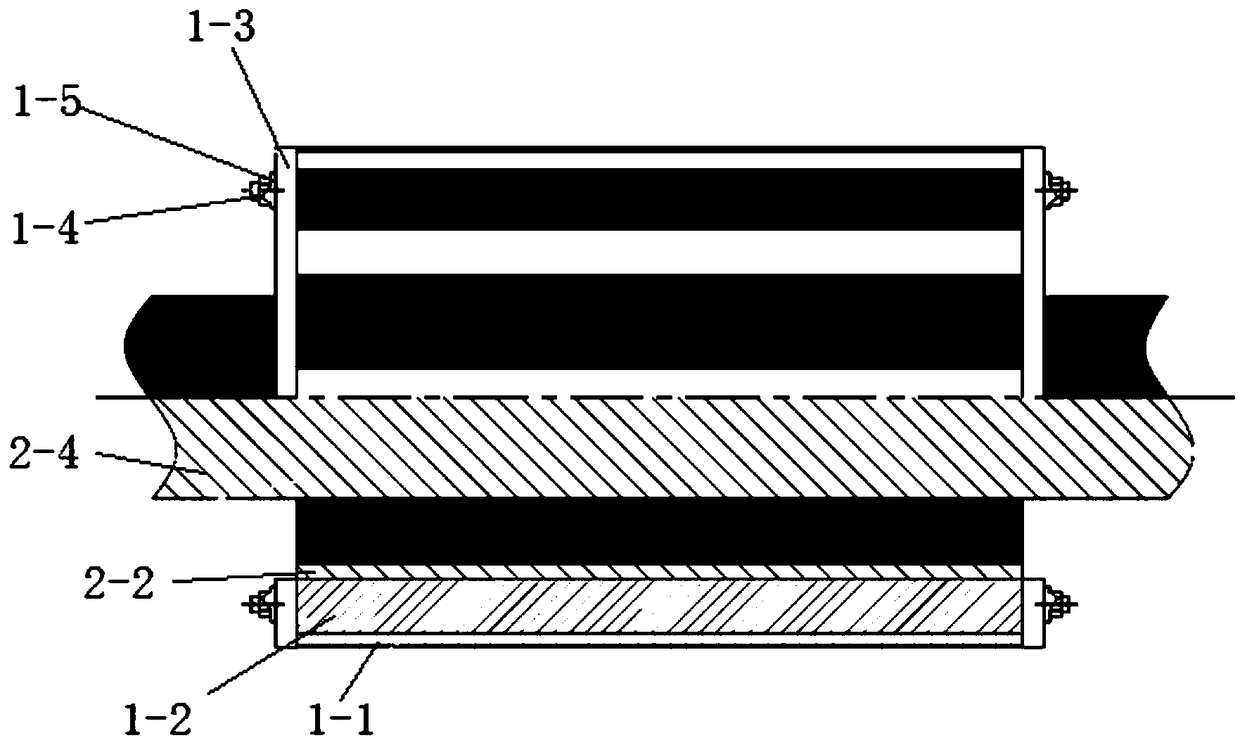
[0022] like figure 1 and figure 2 As shown, the rotor structure of the high-power permanent magnet motor of the present invention includes: a magnetic pole structure 1 and a rotating shaft structure 2; the magnetic pole structure 1 includes: a permanent magnet 1-1, a magnetic pole box 1-2, a pressing plate 1-3, and a pull rod 1-4 , nuts and washers 1-5; the rotating shaft structure 2 includes: a titanium alloy rib plate 2-1, a cylinder 2-2, a supporting rib 2-3, and a rotating shaft 2-4.

[0023] The magnetic pole box 1-2 is made of silicon steel sheets with punching grooves and the pressure plate 1-3 glued and laminated. After evenly applying resin glue on the surface of each silicon steel sheet, stack it with two pressing plates 1-3. The pressing plates 1-3 have the same size as the silicon steel sheet and are placed at both ends. Use two pull rods 1-4 with threads at...


PUM


Abstract

The invention relates to a high-power permanent magnet motor rotor structure, wherein the magnetic pole structure and the rotating shaft structure are interference-fitted and connected. The magnetic pole box is formed by laminating silicon steel sheet with punching groove and pressing plate; a magnetic pole structure is for by a permanent magnet installed in a magnetic pole box, and that permanentmagnet is fix in the magnetic pole box with a coating resin glue to form a permanent magnet pole structure. A magnetic pole of that magnetic pole box structure is adopted in the structure, and the permanent magnet can be effectively protected. The rotating shaft structure welded with supporting ribs and sleeves not only has good strength and rigidity but also reduces the moment of inertia of therotor and improves the starting performance. The permanent magnet pole is fixed by interference, which is convenient to install and fix, avoids using too many bolts, and has good technicality and highreliability. The permanent magnet pole is installed before magnetization, which simplifies the installation process and saves a lot of installation tools compared with the installation after magnetization. The permanent magnet pole is installed before magnetization, which avoids the safety risk caused by the strong attractive force when the pole is installed.

Description

technical field [0001] The invention relates to a permanent magnet motor rotor, in particular to a high-power low-speed permanent magnet motor structure. Background technique [0002] At present, there are two ways to fix the rotor poles of high-power low-speed permanent magnet motors: [0003] The first type: the permanent magnet is directly embedded in the slot of the yoke after being magnetized, which is a rotor structure with a built-in permanent magnet. This method does not require a magnetic pole box, but the disadvantages are: (1) The permanent magnet has a strong magnetic force, and the assembly requires extremely complicated tooling; (2) The permanent magnet assembly process is poor, and the permanent magnet is easily damaged during the assembly process. If there is damage, the overall assembly will fall short; (3) the safety risk in the assembly process is high; (4) the rotor has a large moment of inertia and poor start-up performance. [0004] The second type: t...

Claims


Application Information

Patent Timeline
Patent Type & Authority Applications(China)
IPC IPC(8): H02K1/27H02K1/28
CPCH02K1/274H02K1/28
Inventor 张超杨智李姗赵泰然曹阳黄超
Owner SHANGHAI MARINE EQUIP RES INST
Learn More