
Array substrate, preparation method thereof, and display device

An array substrate and substrate technology, applied in semiconductor/solid-state device manufacturing, electrical components, electric solid-state devices, etc., can solve the problem of reducing the effective area of ​​PIN photodiodes and achieve the effect of reducing dark current and improving signal-to-noise ratio

Active Publication Date: 2019-01-11
BOE TECH GRP CO LTD
View PDF5 Cites 0 Cited by
  • Summary
  • Abstract
  • Description
  • Claims
  • Application Information

AI Technical Summary

Problems solved by technology

Although the secondary etching of the first transparent electrode reduces the dark current, the effective area of ​​the PIN photodiode is also correspondingly reduced.

Method used


Image

  • Array substrate, preparation method thereof, and display device
  • Array substrate, preparation method thereof, and display device
  • Array substrate, preparation method thereof, and display device

Examples


Embodiment Construction

[0077] Example embodiments will now be described more fully with reference to the accompanying drawings. Example embodiments may, however, be embodied in many forms and should not be construed as limited to the embodiments set forth herein; rather, these embodiments are provided so that this disclosure will be thorough and complete, and will fully convey the concept of example embodiments to those skilled in the art. The same reference numerals in the drawings denote the same or similar structures, and thus their detailed descriptions will be omitted.

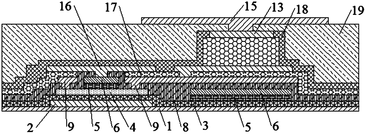
[0078] refer to figure 1 A schematic structural diagram of an array substrate in the related art is shown. After the etching of the source and drain electrodes 9 of the array substrate is completed, the deposition and etching of the first protection layer 17 are performed, and then the deposition and etching of the second source and drain electrodes 16 are performed, and then the deposition and etching of the PIN photodiode a...


PUM


Abstract

The invention relates to the technical field of display, and provides a preparation method of an array substrate. The preparation method of the array substrate comprises the steps of forming a protective layer and forming vias on the protective layer; a photodiode is formed in the via. The photodiode is directly deposited in the via hole of the protective layer, and the sidewall of the photodiodeis bonded with the inner wall of the via hole. During the etching process of the photodiode, the etching gas will not damage the sidewall of the photodiode, the dark current of the photodiode is reduced, and the signal-to-noise ratio is improved. The protective layer can protect the photodiode and play the role of planarization.

Description

technical field [0001] The present invention relates to the field of display technology, in particular to an array substrate, a method for preparing the array substrate, and a display device with the array substrate. Background technique [0002] In the display device in the prior art, during the etching process of the PIN photodiode, the etching gas will cause certain damage to the sidewall of the PIN photodiode, so that the dark current of the PIN photodiode increases and the signal-to-noise ratio decreases. At the same time, in order to reduce the dark current, the first transparent electrode needs to be etched a second time. Although the secondary etching of the first transparent electrode reduces the dark current, the effective area of ​​the PIN photodiode is correspondingly reduced. [0003] Therefore, it is necessary to study a new array substrate, a method for preparing the array substrate, and a display device with the array substrate. [0004] The above informati...

Claims


Application Information

Patent Timeline
Patent Type & Authority Applications(China)
IPC IPC(8): H01L21/77H01L27/12
CPCH01L27/1214H01L27/1259H01L27/1222H01L27/127H01L27/1443
Inventor 王国强
Owner BOE TECH GRP CO LTD
Learn More