Liquid conductivity detection system

A detection system and conductivity technology, applied in the direction of fluid resistance measurement, components of electrical measuring instruments, measuring electricity, etc., can solve the problems of increased application cost, expensive chips, and can not meet the requirements, etc., to reduce hardware costs and simplify The effect of the detection process

Inactive Publication Date: 2019-01-11
湖南宝德机电设备有限公司
View PDF10 Cites 3 Cited by
  • Summary
  • Abstract
  • Description
  • Claims
  • Application Information

AI Technical Summary

Problems solved by technology

[0002] In current liquid conductivity detectors, the AC signal is generally used as the excitation source for its detection. When it is detected, the direct measurement method is generally used to microscopically decompose the AC signal. Within t, the AC signal is a constant value. The effective value is obtained by continuously sampling the AC signal. This method is feasible when the accuracy is not high, but in the case where the accuracy is required In some cases, this approximation method does not meet the requirements
Of course, in addition to this method, a special AC signal acquisition chip can also be used to obtain its effective value, but since this chip is relatively expensive, the application cost will increase significantly

Method used


Image

  • Liquid conductivity detection system
  • Liquid conductivity detection system
  • Liquid conductivity detection system

Examples


Embodiment 2

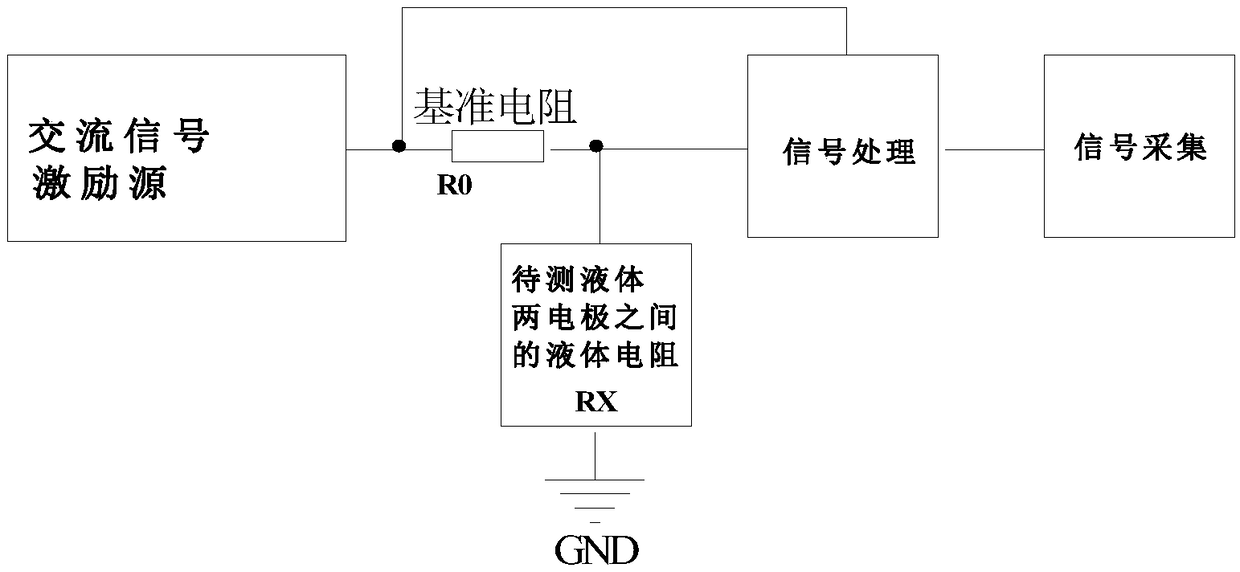
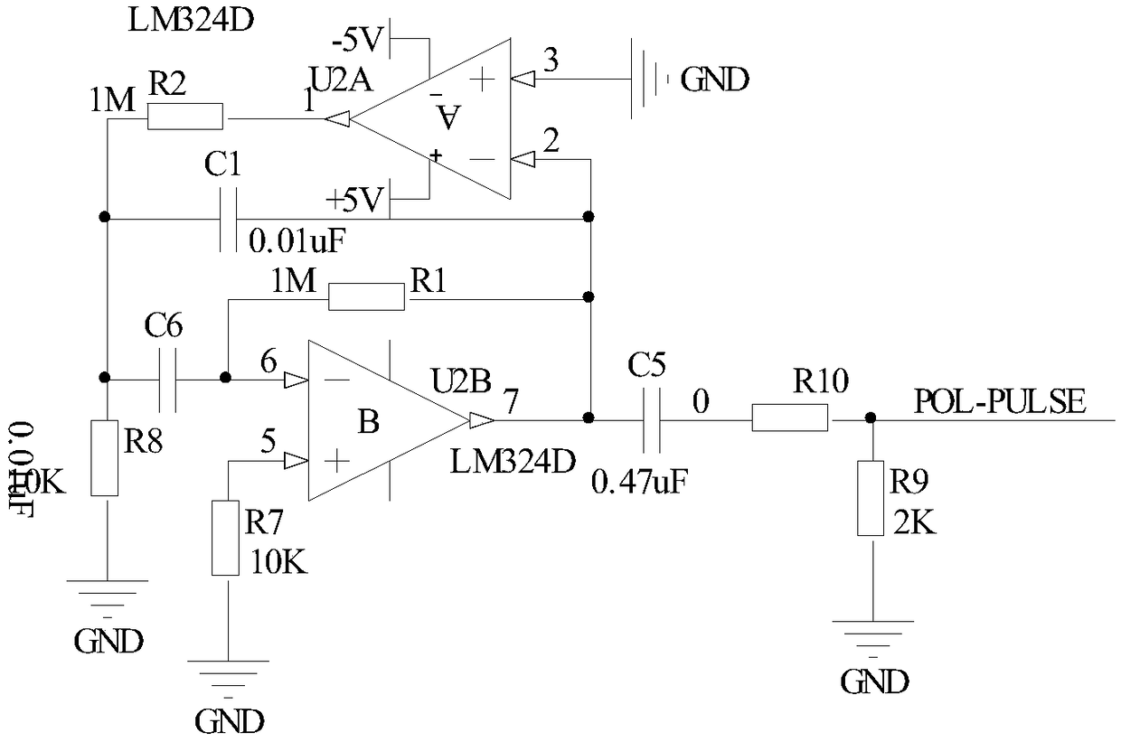
[0019] Embodiment 2: On the basis of Embodiment 1, the AC signal excitation source of this design is as follows figure 2 As shown, including operational amplifier U2A and operational amplifier U2B, pin 3 of operational amplifier U2A is grounded, pin 2 of operational amplifier U2A is connected to resistor R1, capacitor C1, capacitor C5 and pin 7 of operational amplifier U2B, and the other end of capacitor C5 is connected to resistor R10, the other end of resistor R10 is connected to excitation source signal POL-PULSE and resistor R9, pin 1 of operational amplifier U2A is connected to resistor R2, the other end of resistor R2 is connected to capacitor C1, capacitor C6 and resistor R8, and the other end of capacitor C6 is connected to resistor The other end of R1 is connected to the pin 6 of the operational amplifier U2B, and the pin 5 of the operational amplifier U2B is grounded through the resistor R7. In this circuit, an operational amplifier chip LM324 is used to generate a ...

Embodiment 3

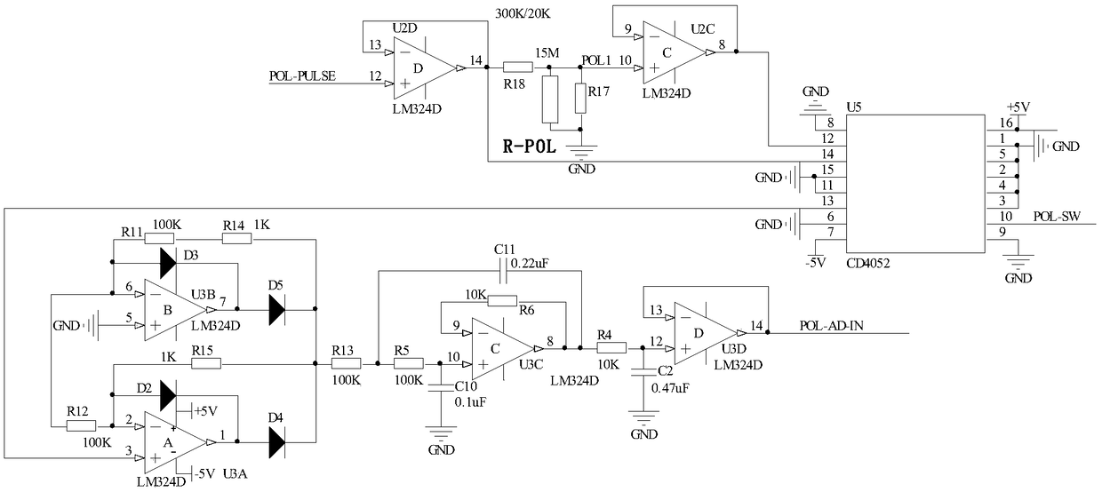
[0020] Embodiment 3, on the basis of embodiment 2, the signal processing circuit of this design is as image 3 As shown, it includes the operational amplifier U2D and the chip U5, the pin 12 of the operational amplifier U2D is connected to the excitation source signal POL-PULSE, the pin 13 of the operational amplifier U2D is connected to the pin 14 of the chip U5, the pin 14 of the operational amplifier U2D and the resistor R18, and the resistor R18 The other end of the resistor R17 is connected to the pin 10 of the operational amplifier U2C, the pin 8 of the operational amplifier U2C is connected to the pin 9 of the operational amplifier U2C and the pin 12 of the chip U5, the pin 13 of the chip U5 is connected to the pin 3 of the operational amplifier U3A, and the operational amplifier U3A Pin 2 of pin 2 is connected to the anode of diode D2, resistor R15 and resistor R12, the other end of resistor R12 is connected to resistor R11, the anode of diode D3, the other end of resis...

Embodiment 4

[0022] Embodiment 4, on the basis of embodiment 3, the signal acquisition circuit of this design is as Figure 4 As shown in the figure, ADS1100 is a 16-bit single-channel AD converter, and ADS-VREF is a 5V reference voltage. After POL-AD-IN is sampled by AD, it is read into the CPU by ADS-SDA and ADS-SCL serial interfaces. Signal Acquisition.


PUM


Abstract

The invention discloses a liquid conductivity detection system. The liquid conductivity detection system comprises an alternating current signal excitation source, a reference resistor, a signal processing unit, a liquid resistor and a signal acquisition unit. The signal acquisition unit is connected with the signal processing unit, and the signal processing unit is further connected with the reference resistor, the liquid resistor and the alternating current signal excitation source. The other end of the liquid resistor is grounded, and the other end of the reference resistor is connected tothe alternating current signal excitation source. The liquid conductivity detection system does not need to detect an effective value of an alternating current signal, thereby simplifying the entire detection process and reducing the hardware cost.

Description

technical field [0001] The invention relates to a conductivity detection system, in particular to a liquid conductivity detection system. Background technique [0002] In current liquid conductivity detectors, the AC signal is generally used as the excitation source for its detection. When it is detected, the direct measurement method is generally used to microscopically decompose the AC signal. Within t, the AC signal is a constant value. The effective value is obtained by continuously sampling the AC signal. This method is feasible when the accuracy is not high, but in the case where the accuracy is required In some cases, this approximate method does not meet the requirements. Of course, in addition to this method, a special AC signal acquisition chip can also be used to obtain its effective value, but since this chip is relatively expensive, the application cost will increase significantly. Contents of the invention [0003] The technical problem to be solved by the ...

Claims


Application Information

Patent Timeline
Patent Type & Authority Applications(China)
IPC IPC(8): G01R27/22G01R1/28
CPCG01R1/28G01R27/22
Inventor 唐勇江四平
Owner 湖南宝德机电设备有限公司
Why Eureka
Try Eureka