
Device and method for rapid scanning and imaging of two-dimensional distribution of pollutant gases

A polluted gas, fast scanning technology, applied in the field of optical measurement, can solve the problem that the two-dimensional distribution of polluted gas cannot be visualized directly, and cannot achieve no interval imaging, etc., and achieves no interval two-dimensional distribution, good imaging quality, and high resolution. rate effect

Inactive Publication Date: 2019-01-11
HEFEI INSTITUTES OF PHYSICAL SCIENCE - CHINESE ACAD OF SCI
View PDF3 Cites 6 Cited by
  • Summary
  • Abstract
  • Description
  • Claims
  • Application Information

AI Technical Summary

Problems solved by technology

[0003] Imaging telemetry technology based on differential absorption spectroscopy is a passive measurement technology that uses scattered light from the sun. It is mainly used to obtain the two-dimensional distribution of the concentration of polluted gas oblique columns, and can quickly and accurately locate the scattered sources of pollution in a large area. ; However, it is impossible to quickly image the two-dimensional distribution information of conventional pollutant gases in the region without intervals, and at the same time, the two-dimensional distribution of pollutant gases cannot be visualized directly

Method used


Image

  • Device and method for rapid scanning and imaging of two-dimensional distribution of pollutant gases
  • Device and method for rapid scanning and imaging of two-dimensional distribution of pollutant gases
  • Device and method for rapid scanning and imaging of two-dimensional distribution of pollutant gases

Examples


Embodiment Construction

[0035] Combine below Figure 1-Figure 4 , the present invention is described in further detail.

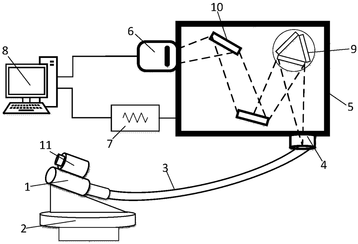
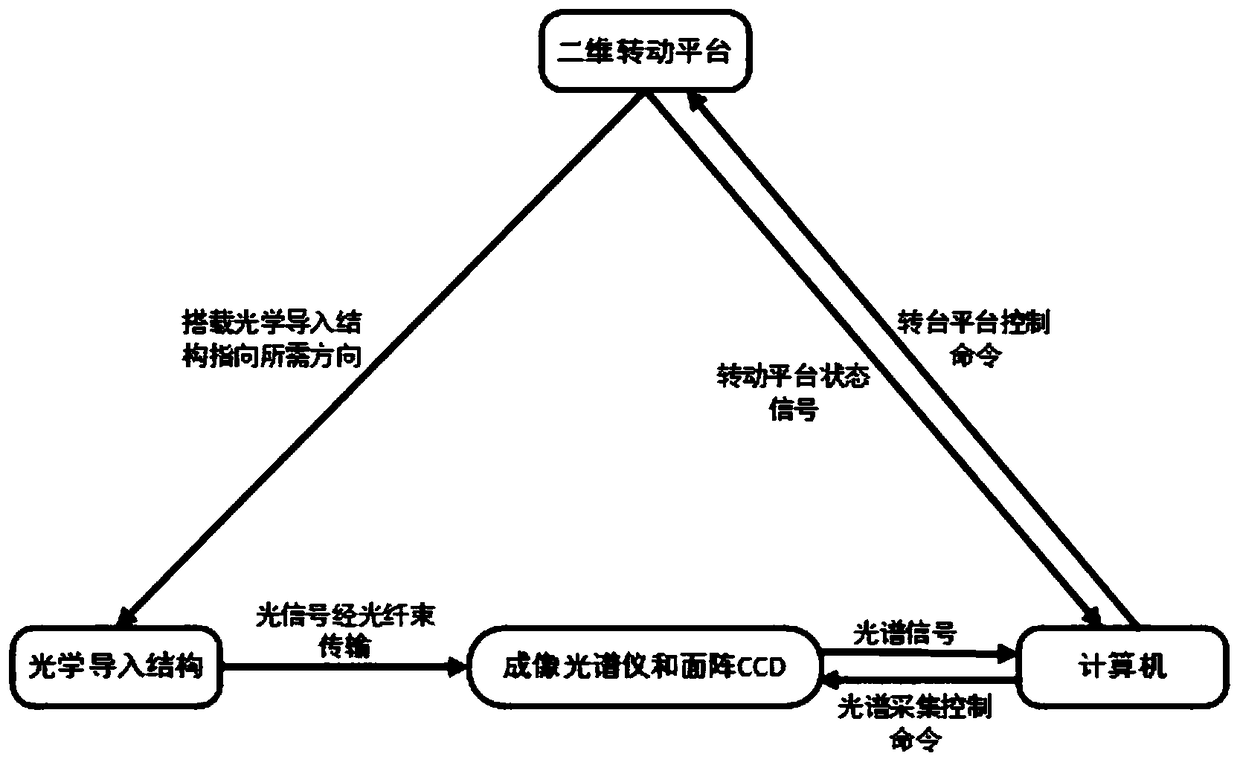
[0036] As shown in the figure, the fast scanning imaging device includes a front optical system, an introduction optical system, an imaging spectrometer 5 , an area array CCD detector 6 and a computer 8 .

[0037] in:

[0038] The front optical system includes an objective lens 1 with a certain field of view and a camera 11 arranged coaxially with the objective lens 1, and the objective lens and the camera are fixed on a two-dimensional rotating platform.

[0039] The introduction optical system is an introduction optical system incorporating a multi-core optical fiber bundle 3 .

[0040] The imaging spectrometer 5 is a Czerny-turner structured imaging spectrometer with aberrations eliminated. The optical system in the imaging spectrometer 5 includes an incident slit 4, a collimating mirror, a reflective grating 9, and a focusing mirror 10, wherein the reflective grating 9 is a ...


PUM


Abstract

The invention relates to a device and method for rapid scanning and imaging of two-dimensional distribution of pollutant gases. A front optical system receives a sun scattered light passing through the pollutant gases, and the sun scattered light is coupled through an introduction optical system, and then enters an imaging spectrometer, and is received by an area array CCD detector after being dispersed by the imaging spectrometer; the area array CCD detector completes the spectrum acquisition work of a spectral dimension and a spatial dimension, and transmits to a computer through a USB afterdigitization; the computer uses a differential absorption spectroscopy analysis method to performing inversion, so as to obtain detected slant column concentration of the pollutant gases in differentspatial dimensions; and the concentration information is matched with pixels on the spatial dimension according to a geometric model of an observation angle and sequentially reconstructed according to the scanning direction, so that the two-dimensional concentration field distribution of the pollutant gas is quickly scanned and imaged without an interval. The invention realizes the rapid imagingof the two-dimensional distribution information of conventional pollutant gases in the area without the interval, which is beneficial for determining the position information and conveying situation of each scattered source in the area, and provides technical support for the environmental protection department to grasp the position situation of each scattered source in the area.

Description

technical field [0001] The invention relates to the technical field of optical measurement, in particular to a device and method for rapid scanning and imaging of two-dimensional distribution of polluted gas. Background technique [0002] In recent years, China's economy has developed rapidly and will continue to develop rapidly in the future. The resulting air pollution has an increasingly serious impact on people's daily life. At the same time, various air pollution gas monitoring technologies have also made great progress. Compared with the fixed-point sampling chemical analysis method, the advantage of the optical telemetry method is that it has the characteristics of long-distance, multi-component, high-resolution and continuous real-time observation. [0003] Imaging telemetry technology based on differential absorption spectroscopy is a passive measurement technology that uses scattered light from the sun. It is mainly used to obtain the two-dimensional distribution o...

Claims


Application Information

Patent Timeline
Patent Type & Authority Applications(China)
IPC IPC(8): G01N21/31G01N21/33G01N21/01
CPCG01N21/01G01N21/31G01N21/33
Inventor 谢品华吴子扬李昂徐晋胡肇焜陈浩方武
Owner HEFEI INSTITUTES OF PHYSICAL SCIENCE - CHINESE ACAD OF SCI
Learn More