Novel spring plate damper

A shock absorber, spring plate technology, applied in the direction of spring/shock absorber, shock absorber, shock absorber, etc., can solve the problems of engine damage, vibration reduction technology can not meet the requirements, engine shock and vibration, etc. The effect of suppressing vibration, simple structure, and reliable shock absorption

Pending Publication Date: 2019-01-11
YANCHENG DITING AUTO PARTS CO LTD
View PDF0 Cites 0 Cited by
  • Summary
  • Abstract
  • Description
  • Claims
  • Application Information

AI Technical Summary

Problems solved by technology

[0002] There are many kinds of construction machinery, such as bulldozers, excavators, etc. The working environment of construction machinery is generally more complicated, mostly in mines, coal yards and water conservancy projects. Sometimes the shock and vibration generated by the engine will be very large, which will cause damage to the engine. With the improvement of people's requirements for the performance of construction machinery, the traditional vibration reduction technology is increasingly unable to meet the requirements, and it is imperative to adopt new vibration reduction technology

Method used


Image

  • Novel spring plate damper
  • Novel spring plate damper
  • Novel spring plate damper

Examples


Embodiment Construction

[0017] The present invention will be further explained below in conjunction with the accompanying drawings and specific embodiments. It should be understood that the following specific embodiments are only used to illustrate the present invention and are not intended to limit the scope of the present invention. It should be noted that the words "front", "rear", "left", "right", "upper" and "lower" used in the following description refer to the directions in the drawings, and the words "inner" and "outer ” refer to directions towards or away from the geometric center of a particular part, respectively.

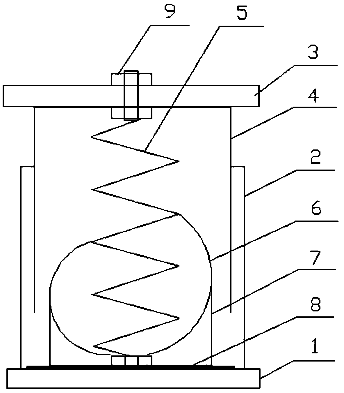
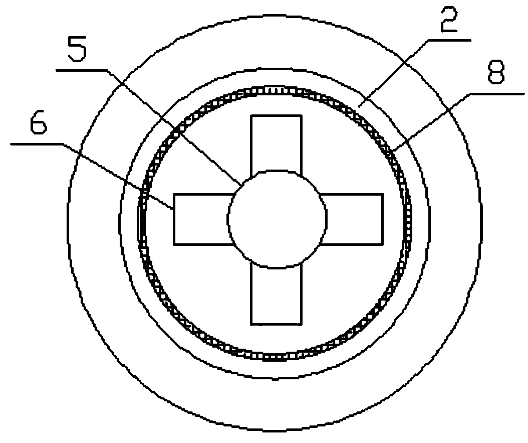
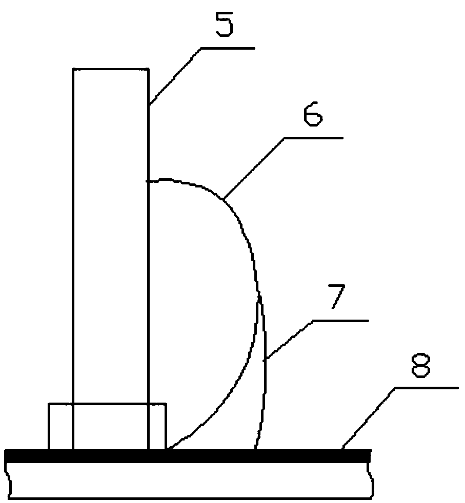
[0018] As shown in the figure, a new spring plate shock absorber according to the present invention includes an upper shock absorber cover, a lower shock absorber cover, a spring plate 6, and a spring 5, and the lower shock absorber cover includes a bottom plate 1 and a limit plate 2. The limit plate 2 is tube-shaped, vertically arranged on the bottom plate, and the top of the ...


PUM


Abstract

The invention discloses a novel spring plate damper. The novel spring plate damper comprises an upper damping cover, a lower damping cover, four spring plates, and a spring. The lower damping cover comprises a bottom plate and a limiting plate. The limiting plate is in a tubular shape, and is vertically arranged at the bottom plate. The upper damping cover comprises a top plate and a guide plate.The diameter of the guide plate is less than that of the limiting plate. The guide plate is arranged in the limiting plate. The spring is fixed between the top plate and the bottom plate. The four spring plates are uniformly arranged outside the spring. The spring plates are in a concave arc shape. The upper ends of the spring plates are connected with the middle of the spring. The lower portionsof the spring plates are connected with the bottom of the spring. Small holes are formed in the arc tops of the spring plates. Damping wires are arranged in the small holes. Rubber layers are arrangedon the inner side of the limiting plate and the surface of the bottom plate. The lower ends of the damping wires are arranged on the rubber layer of the surface of the bottom plate. The structure issimple and application is convenient. Impact can be absorbed in an omnibearing mode, shock is restrained, quick damping is achieved, rotation of a motor is more stable, and damping is more reliable.

Description

technical field [0001] The invention belongs to the technical field of shock absorbers, and in particular relates to a novel spring plate shock absorber. Background technique [0002] There are many kinds of construction machinery, such as bulldozers, excavators, etc. The working environment of construction machinery is generally more complicated, mostly in mines, coal yards and water conservancy projects. Sometimes the shock and vibration generated by the engine will be very large, which will cause damage to the engine. With the improvement of people's requirements for the performance of construction machinery, the traditional vibration reduction technology is increasingly unable to meet the requirements, and it is imperative to adopt new vibration reduction technology. Contents of the invention [0003] In order to solve the above problems, the present invention discloses a novel spring plate shock absorber, which has a simple structure and is easy to use, and can realiz...

Claims


Application Information

Patent Timeline
Patent Type & Authority Applications(China)
IPC IPC(8): F16F7/00
CPCF16F7/00
Inventor 郭风金
Owner YANCHENG DITING AUTO PARTS CO LTD
Why Eureka
Try Eureka