
Intelligent window with indoor temperature monitoring function

An indoor temperature and smart window technology, applied in the field of smart windows, can solve problems such as control, window frame corrosion, and window frame cracking, and achieve the effects of increasing adjustment fun, prolonging service life, and facilitating adjustment and use

Pending Publication Date: 2019-01-11
东莞市同窗智能科技有限公司
View PDF0 Cites 0 Cited by
  • Summary
  • Abstract
  • Description
  • Claims
  • Application Information

AI Technical Summary

Problems solved by technology

[0004] The object of the present invention is to provide a smart window with indoor temperature monitoring function to solve the problem that although the existing smart window proposed in the background technology has a certain photosensitive function, the window frame of such a smart window is usually directly covered with cement. It is poured and fixed with the wall substrate, and the surroundings of the window frame are easily affected by the moisture brought by the water pipe installed inside the wall substrate, thereby corroding the window frame, and such a single pouring connection method will cause the corroded window frame to break , resulting in the looseness of the smart window, which affects the normal use of the user. The existing smart window cannot check and monitor the surrounding temperature, which is not conducive to the user's control of the indoor temperature. The smart window cannot provide LED display and natural transparency at the same time. There are two different effects of the light window, causing the problem that the user's adjustment range is narrow

Method used


Image

  • Intelligent window with indoor temperature monitoring function
  • Intelligent window with indoor temperature monitoring function
  • Intelligent window with indoor temperature monitoring function

Examples


Embodiment Construction

[0026] The following will clearly and completely describe the technical solutions in the embodiments of the present invention with reference to the accompanying drawings in the embodiments of the present invention. Obviously, the described embodiments are only some, not all, embodiments of the present invention. Based on the embodiments of the present invention, all other embodiments obtained by persons of ordinary skill in the art without making creative efforts belong to the protection scope of the present invention.

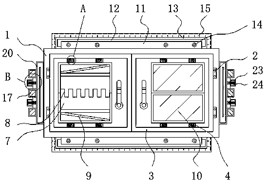
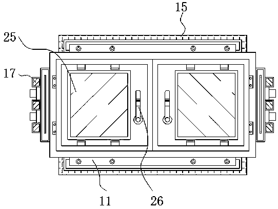
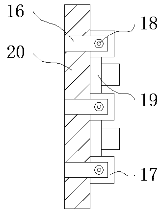
[0027] see Figure 1-5 , the present invention provides a technical solution: a smart window with indoor temperature monitoring function, including a window frame body 1, a hinge 2, a window frame 3, a connecting block 4, an engaging groove 5, an engaging block 6, a display Screen frame 7, connecting tooth 8, support rod 9, display screen body 10, fixing strip 11, sliding groove 12, fixing platform 13, fixing bolt 14, sealing ring 15, limit rod 16, limit block...


PUM


Abstract

The invention relates to an intelligent window with an indoor temperature monitoring function, which comprises a window frame body, a clamping block and a fixing bar, wherein a hinge is arranged inside the window frame body through a bolt and a screw hole; the inner side of the hinge is provided with a sub window frame; the sub window frame is internally fixed with a connecting block; the connecting block is internally provided with a clamping groove; the clamping block is slidably connected inside the clamping groove; the lower end of the clamping block is fixed with a display screen frame; connecting teeth are engaged between the display screen frames; the connecting teeth are internally provided with a supporting rod; and the front end of the display screen frame is provided with a display screen body. According to the intelligent window with the indoor temperature monitoring function disclosed in the invention, the connecting block and the clamping block form a clamping structure through the clamping groove, the clamping block can be in clamped connection with the connecting block through the clamping groove, connection between the display screen frames and the connecting blockis fixed, the display screen body can be assembled and disassembled conveniently, and adjustment and use by a user can be better facilitated.

Description

technical field [0001] The invention relates to the technical field of smart windows, in particular to a smart window with an indoor temperature monitoring function. Background technique [0002] A window, in architecture, refers to an opening made in a wall or roof to allow light or air to enter the room. In fact, the original meaning of window and door refers to window and door respectively, that is, to leave a hole on the wall, and inside the frame is a window lattice, which can transmit light and smoke. Smart window is a window made of light-sensitive and color-changing materials. , as environmental protection and energy saving are increasingly valued, the rational use of energy and the research and development of energy-saving products have made great progress. [0003] Although the existing smart windows have a certain light-sensitive function, usually the window frames of such smart windows are directly poured and fixed between the cement and the wall substrate, and ...

Claims


Application Information

Patent Timeline
Patent Type & Authority Applications(China)
IPC IPC(8): E06B3/36E06B7/28E06B1/60E06B1/62G09F9/33
CPCE06B3/36E06B1/60E06B1/62E06B7/28G09F9/33
Inventor 黄高欢
Owner 东莞市同窗智能科技有限公司
Learn More