Textile cloth dividing device

A technology for textile fabrics and fabric racks, which is applied in the field of textile fabric dividing devices, which can solve problems such as rough edges at the dividing opening, specifications that do not strictly meet the buyer's requirements, and inconvenient use, so as to achieve the effect of neatly dividing the opening

Inactive Publication Date: 2019-01-11
射阳县汇佳纺织有限公司
View PDF0 Cites 1 Cited by
  • Summary
  • Abstract
  • Description
  • Claims
  • Application Information

AI Technical Summary

Problems solved by technology

[0002] When the fabric is processed, it is all done on the assembly line. The processed textile fabric needs to be cut into the specifications required by the seller. The previous cutting was done manually. Due to the large size of the cloth, it requires a lot of manual work, and the cutting The specifications that come out are not strictly in line with the size required by the buyer, so there is the current split device
[0003] In some large factories, their machinery and equipment are relatively advanced, and the cloth has been divided before it is produced, but in small processing factories, they do not have advanced equipment, and many of them use dividing devices for division, but the traditional division The device basically uses a sliding knife to divide, but the textile fabric is soft, and it can only be divided when it is tensioned by an external force during division. Once the force is uneven, when the textile fabric is divided, the division mouth will have rough edges. inconvenient

Method used


Image

  • Textile cloth dividing device
  • Textile cloth dividing device
  • Textile cloth dividing device

Examples


Embodiment Construction

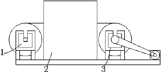
[0022] Such as Figure 1-4 As shown, a textile cloth dividing device includes a textile cloth dividing device, including a cloth releasing device 1, a dividing device 2 and a cloth receiving device 3, the top of the cloth releasing device 1 is fixedly equipped with a dividing device 2, and the top of the cloth releasing device 1 A dividing device 2 is fixedly installed, and a cloth receiving device 3 is fixedly installed on the top of the cloth releasing device 1 .

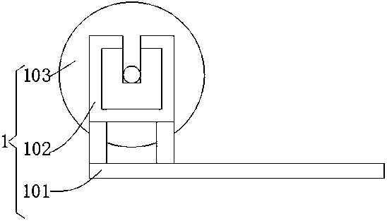
[0023] The cloth releasing device 1 comprises a base 101, a cloth releasing frame 102 is fixedly mounted on the top of the base 101, and a cloth releasing wheel 103 is movably connected to the inside of the cloth releasing frame 102.

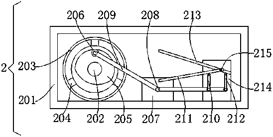
[0024] Separation device 2 comprises casing 201, and the left arm of casing 201 is provided with the strip-shaped through hole that matches with textile cloth, and the right arm of casing 201 is provided with the strip-shaped through hole that matches with textile cloth, and the bot...


PUM


Abstract

The invention provides a textile cloth dividing device, relates to the technical field of the textile cloth dividing device and aims to achieve the effect of cutting cloth through imitating the way ofscissors, achieve division without being tightened through external forces and achieve neat division edges. The device includes a laying device, a dividing device and a cloth collecting device, wherein the top of the laying device is fixedly equipped with the dividing device, and the top of the laying device is fixedly equipped with the cloth collecting device. The device is advantaged in that arotation disc is driven by a motor to rotate, a track is driven by the rotation disc through a connection rod to rotate, when convex blocks of the track contact with rotation wheels, the top of the rotation wheels moves downwards, the top of a support rod is made to move downwards, a bolt acts as a lever, the other end of the support rod rotates upwards, a first cutting plate and a second cuttingplate are meshed, so the cloth is divided, division can be achieved without being tightened through external forces, and the division edges are neat.

Description

technical field [0001] The invention relates to the technical field of woven fabric dividing devices, in particular to a textile fabric dividing device. Background technique [0002] When fabrics are processed, they are all assembly line work. The processed textile fabrics need to be cut into the specifications required by the seller. Previously, the cutting was done manually. Due to the large size of the cloth, a lot of labor is required to complete it, and the cutting The specifications that come out are not strictly in line with the size required by the buyer, so there is the current dividing device. [0003] In some large factories, their machinery and equipment are relatively advanced, and the cloth has been divided before it is produced, but in small processing factories, they do not have advanced equipment, and many of them use dividing devices for division, but the traditional division The device basically uses a sliding knife to divide, but the textile fabric is so...

Claims


Application Information

Patent Timeline
Patent Type & Authority Applications(China)
IPC IPC(8): D06H7/02
CPCD06H7/02
Inventor 程祥
Owner 射阳县汇佳纺织有限公司
Why Eureka
Try Eureka