
Emergency manual slow-descenting device and lifting equipment thereof

A slow-down and gentle technology, applied in elevators, transportation and packaging, etc., can solve problems such as hidden safety hazards, high speed, wear of friction plates, etc., and achieve the effect of low maintenance cost, low wear resistance and high efficiency

Active Publication Date: 2019-01-11
CONSTR MECHANIZATION INST CHINESE ACAD OF ARCHITECTURE SCI +1
View PDF10 Cites 6 Cited by
  • Summary
  • Abstract
  • Description
  • Claims
  • Application Information

AI Technical Summary

Problems solved by technology

This approach has great safety hazards. The strength and duration of manually opening the brake are not easy to control. If the operation is improper, the lifting equipment will easily fall to the bottom or cause the anti-fall safety device of the lifting equipment to lock up, making the carrying device of the lifting equipment completely It cannot descend, but it increases the difficulty of escape for the personnel in the carrying device of the lifting equipment
[0003] The methods or devices disclosed in Chinese patent applications CN201510010340, CN201310350510 and CN201110185826 can only deal with the power failure of the lifting equipment, and cannot make the lifting equipment slow down manually when an electrical failure occurs in the lifting equipment.
[0004] Chinese patent application CN200920301560 discloses a constant-velocity lowering device for a construction hoist. The device is a mechanical centrifugal emergency manual slow-down device. Limit the speed of the motor, so as to control the uniform and slow descent of the carrier of the lifting equipment, but the friction plate will be worn after use and needs to be checked and replaced
Moreover, since there is no clutch mechanism, when it is applied to medium-speed and high-speed lifting equipment, the combined speed of the dynamic and static friction plates must be increased due to the higher motor speed, which makes the speed of the emergency manual descent of the carrying device too fast, which is not safe. On the contrary, it cannot be guaranteed

Method used


Image

  • Emergency manual slow-descenting device and lifting equipment thereof
  • Emergency manual slow-descenting device and lifting equipment thereof
  • Emergency manual slow-descenting device and lifting equipment thereof

Examples


Embodiment 1

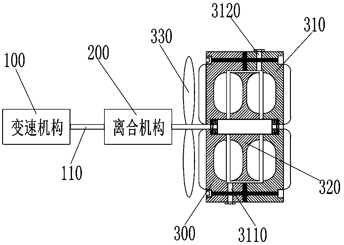
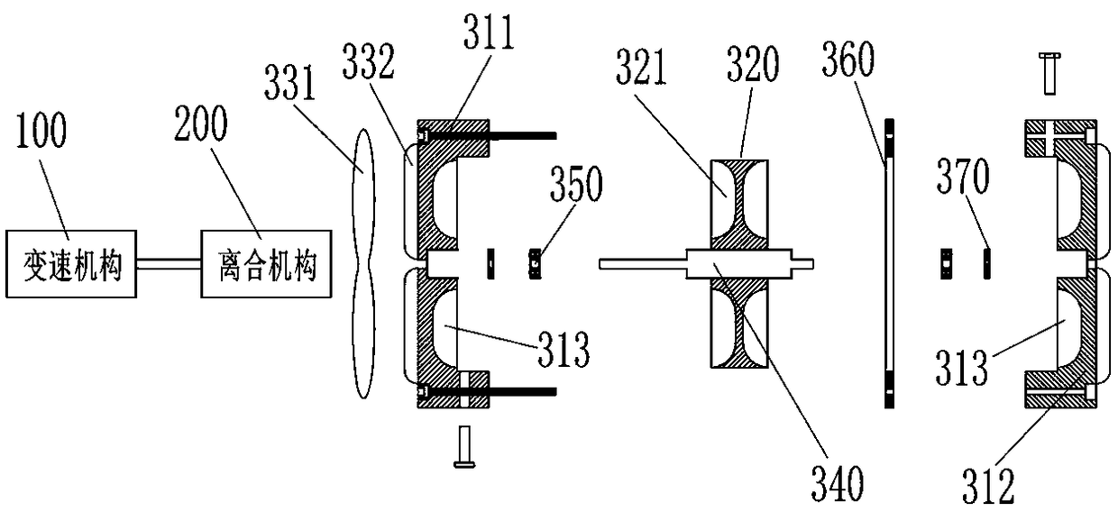
[0036] like figure 1 , figure 2 As shown, an emergency manual slow down device includes a speed change mechanism 100, a clutch mechanism 200 and a slow down mechanism 300. The output end of the speed change mechanism 100 is connected to the clutch mechanism 200 through a high-speed shaft 110. The input end is connected with the clutch mechanism 200 through the input shaft 340 (the clutch mechanism 200 is a mechanical clutch or an electromagnetic clutch, and the effect of the clutch mechanism 200 is to combine and separate the damping effect of the slow-down mechanism 300 and the high-speed shaft of the transmission mechanism 100, The damping effect is not transmitted to the transmission mechanism 100 when the lifting equipment is in normal operation, and the damping effect is transmitted to the transmission mechanism 100 when an emergency manual slow down is required). The slow-down mechanism 300 includes a housing 310, a rotor 320 disposed in the housing 310 and connected t...

Embodiment 2

[0039] like image 3 As shown, the difference between Embodiment 2 and Embodiment 1 is that: the rotor 320 includes a first rotor 3210 and a second rotor 3220, and the first rotor 3210 is connected to the second rotor 3220 through a reversing gear 380. The first rotor 3210 is provided with inclined or vertical first blades 321 , and the second rotor 3220 is provided with inclined or vertical second blades 313 . The first rotor 3210 drives the damping fluid in the sealed cavity to rotate at a high speed through the first blade 321; at the same time, the first rotor 3210 drives the second rotor 3220 to rotate in the opposite direction through the reversing gear 380, and the second blade 313 is relatively opposite to the first rotor 3210. One blade 321 moves in the opposite direction, and transmits the damping effect to the first rotor 3210 through the damping fluid. As the rotating speed increases, the damping effect also increases continuously, and finally reaches a balance.

Embodiment 3

[0041] like Figure 4 As shown, the difference between the third embodiment and the second embodiment is that the speed change mechanism 100 and the clutch mechanism 200 are located on both sides of the slow down mechanism 300 respectively, and the high speed shaft 110 at the output end of the speed change mechanism 100 and the slow down mechanism The input shaft 340 at the input end of 300 is directly connected, and the first rotor 3210 is arranged on the input shaft 340; there is a certain distance between the second rotor 3220 and the first rotor 3210, and the second rotor 3220 is installed axially with the input shaft 340 On the same fixed shaft 390 , the fixed shaft 390 is directly connected with the clutch mechanism 200 . When the damping effect of the slow-down mechanism 300 is needed, the fixed shaft 390 connected to the second rotor 3220 at the non-input end of the slow-down mechanism is locked with the clutch mechanism 200, and the first rotor 3210 drives the airtigh...


PUM


Abstract

The invention discloses an emergency manual slow-descenting device and lifting equipment thereof. The emergency manual slow-descenting device comprises a speed change mechanism, a clutch mechanism anda slow-descenting mechanism, wherein the clutch mechanism is connected to the output end of the speed change mechanism through a high-speed shaft; the clutch mechanism is connected to the input end of the slow-descenting mechanism through an input shaft; the slow-descenting mechanism comprises a shell and a rotor, and the rotor is arranged in the shell and is connected with the input shaft; and the input shaft can freely rotate in the shell through a bearing arranged in the shell; and the rotor is provided with a first blade, and damping liquid is placed in the shell. Through the cooperativeaction of the speed change structure, the clutch mechanism and the slow-descenting mechanism, and the emergency manual slow-descenting device can be fully applicable to the low-speed, medium-speed andhigh-speed lifting equipment and enables the emergency slow-descenting of the lifting equipment to have the advantages of high efficiency, safety, stability, low noise, abrasion resistance and low maintenance cost.

Description

technical field [0001] The invention belongs to the technical field of high-altitude safety, and in particular relates to an emergency manual slow-down device and lifting equipment thereof. Background technique [0002] The main function of lifting equipment is to transport people or goods to high altitude along the guide rail frame. It is mainly composed of guide rail frame, carrying device and transmission mechanism. The guide rail frame is installed with a rack along the vertical direction. The transmission mechanism includes a drive frame, a drive motor with a speed change mechanism, and a drive gear. The transmission mechanism is connected with the carrier. The meshing of the gear and the rack drives the carrying device to run up and down. Since the lifting equipment is generally installed on a construction site with high use intensity, in a relatively remote fan tower or in a bridge tower chimney with a small space, when the lifting equipment is used in these places, ...

Claims


Application Information

Patent Timeline
Patent Type & Authority Applications(China)
IPC IPC(8): B66B5/28
CPCB66B5/282
Inventor 肖洪涛赵涛高娟
Owner CONSTR MECHANIZATION INST CHINESE ACAD OF ARCHITECTURE SCI
Learn More