
Cranial drill for neurosurgical operation

A technique for neurosurgery and surgery, which is applied in the field of cranial drills, can solve problems affecting the accuracy of craniotomy, inconvenient adjustment of drilling angle, patient fixation, etc., to improve stability and safety, improve drilling field of view, The effect of preventing accidental offset

Inactive Publication Date: 2019-01-11
王术茂
View PDF8 Cites 0 Cited by
  • Summary
  • Abstract
  • Description
  • Claims
  • Application Information

AI Technical Summary

Problems solved by technology

[0002] Neurosurgery medical staff often use cranial drills when performing craniotomy on patients. The current cranial drills are all hand-held, requiring medical staff to manually control the accuracy, labor-intensive, and insufficient stability; Chinese invention patent (CN201510172773 .2) A cranial drill for neurosurgery is disclosed. The body is raised to the upper part of the box through a hand-operated telescopic device. Align the drill bit with the drilling site, and then input the drilling depth and other parameters through the programmable logic controller, and the electric telescopic device can automatically execute the commands of the programmable logic controller to automatically complete the drilling operation
However, this device cannot fix the patient. If the medical staff accidentally touches the patient's body, the head will shift and affect the accuracy of the craniotomy. During the cranial process, the drill bit will bring out a large amount of debris such as skin flakes, meat flakes, and bone flakes, which will pollute the environment, and some will stick to the drill hole, causing certain interference to the line of sight

Method used


Image

  • Cranial drill for neurosurgical operation
  • Cranial drill for neurosurgical operation
  • Cranial drill for neurosurgical operation

Examples


Embodiment Construction

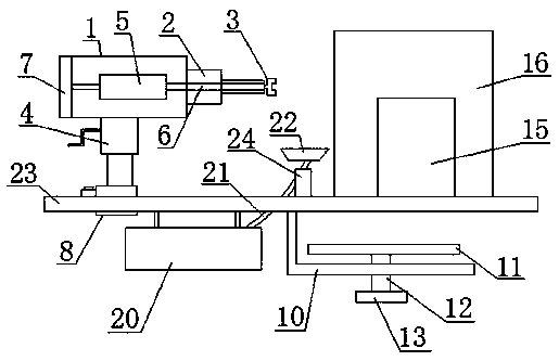
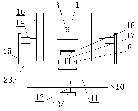
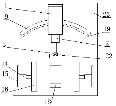
[0015] refer to Figure 1-3 , a cranial drill for neurosurgery, comprising a fuselage 1; the front end of the fuselage 1 is connected to a drill bit clamping device 3 through an electric telescopic device 2, and the bottom end of the fuselage 1 is connected to a hand-operated telescopic device 4, so The body 1 is provided with a servo motor 5, the servo motor 5 is connected to the electric telescopic device 2 through a connecting shaft 6, and the rear end of the body 1 is provided with a programmable logic controller electrically connected to the servo motor 5 7; The height of the vertical direction of the body 1 can be adjusted through the hand-operated telescopic device 4, the drill bit is installed on the drill bit clamping device 3, and then parameters such as the depth of the drill skull are input through the programmable logic controller 7, and the electric telescopic device 2. The command of the programmable logic controller 7 can be automatically executed to complete t...


PUM


Abstract

The invention discloses a cranial drill for neurosurgical operation, comprising a device body, wherein the front end of the device body is connected with a drill bit clamping device through an electric telescopic device, the bottom end of the device body is connected with a hand-rocking telescopic device, a servo motor is arranged in the device body, the servo motor is connected with the electrictelescopic device through a connecting shaft, and the rear end of the device body is provided with a programmable logic controller which is connected with the servo electric machine; the bottom end ofthe manual telescopic device is connected with a slide; two telescopic tubes are arranged at the front of the horizontal plate, the outer side of the telescopic tube is connected with the baffle plate on the horizontal plate, and the inner side of the telescopic tube is connected with the head splint; the transverse plate is provided with two telescopic connecting rods arranged in front and backbetween the two head splints; and the top end of the telescopic connecting rods is connected with a cushion block. The invention can fix the head of the patient, and is convenient to adjust the angleand absorb the debris generated by the drill skull.

Description

technical field [0001] The invention relates to the field of cranial drills, in particular to a cranial drill for neurosurgery. Background technique [0002] Neurosurgery medical staff often use cranial drills when performing craniotomy on patients. The current cranial drills are all hand-held, requiring medical staff to manually control the accuracy, labor-intensive, and insufficient stability; Chinese invention patent (CN201510172773 .2) A cranial drill for neurosurgery is disclosed. The body is raised to the upper part of the box through a hand-operated telescopic device. Align the drill bit with the drilling site, and then input parameters such as the drilling depth through the programmable logic controller, and the electric telescopic device can automatically execute the commands of the programmable logic controller to automatically complete the drilling operation. However, this device cannot fix the patient. If the medical staff accidentally touches the patient's body...

Claims


Application Information

Patent Timeline
Patent Type & Authority Applications(China)
IPC IPC(8): A61B17/16A61G13/12A61B90/14
CPCA61B17/1695A61B90/14A61G13/121
Inventor 王术茂
Owner 王术茂
Learn More