
A construction drilling device

A drilling device and construction technology, applied in drilling/drilling equipment, drill repair, workbench, etc., can solve the problems of power consumption, inconvenient transportation, labor-intensive personnel, etc., to solve the problem of flying dust, simple and fast operation , to avoid the effect of route deviation

Active Publication Date: 2022-07-26
于泉
View PDF9 Cites 0 Cited by
  • Summary
  • Abstract
  • Description
  • Claims
  • Application Information

AI Technical Summary

Problems solved by technology

[0004] (1) Most of the existing construction drilling devices need to manually control the movement of the drilling rig to complete the drilling work, but this method not only consumes the physical strength of the construction personnel, but also shifts during the moving process, which leads to the drilling route Deviations occur; in addition, in the work of transporting the drilling rig, the way the hand-held drilling rig moves consumes physical strength and is not convenient for transportation;
[0005] (2) When drilling holes, there will be burrs at the end of the holes. This phenomenon will not only affect the forming effect of the hole pattern, but also affect the later decoration work;
[0006] (3) With the existing construction drilling device, when processing holes at higher positions, the dust generated will float indoors from top to bottom, which will cause construction workers to inhale too much dust, and a large amount of dust will enter into the device;
[0007] (4) Existing construction drilling devices usually require additional water pumps to complete the water injection work during water injection construction. This method requires the use of other electrical equipment, so additional power will be consumed

Method used


Image

  • A construction drilling device
  • A construction drilling device
  • A construction drilling device

Examples


Embodiment Construction

[0035] The technical solutions in the embodiments of the present invention will be clearly and completely described below with reference to the accompanying drawings in the embodiments of the present invention. Obviously, the described embodiments are only a part of the embodiments of the present invention, rather than all the embodiments. Based on the embodiments of the present invention, all other embodiments obtained by those of ordinary skill in the art without creative efforts shall fall within the protection scope of the present invention.

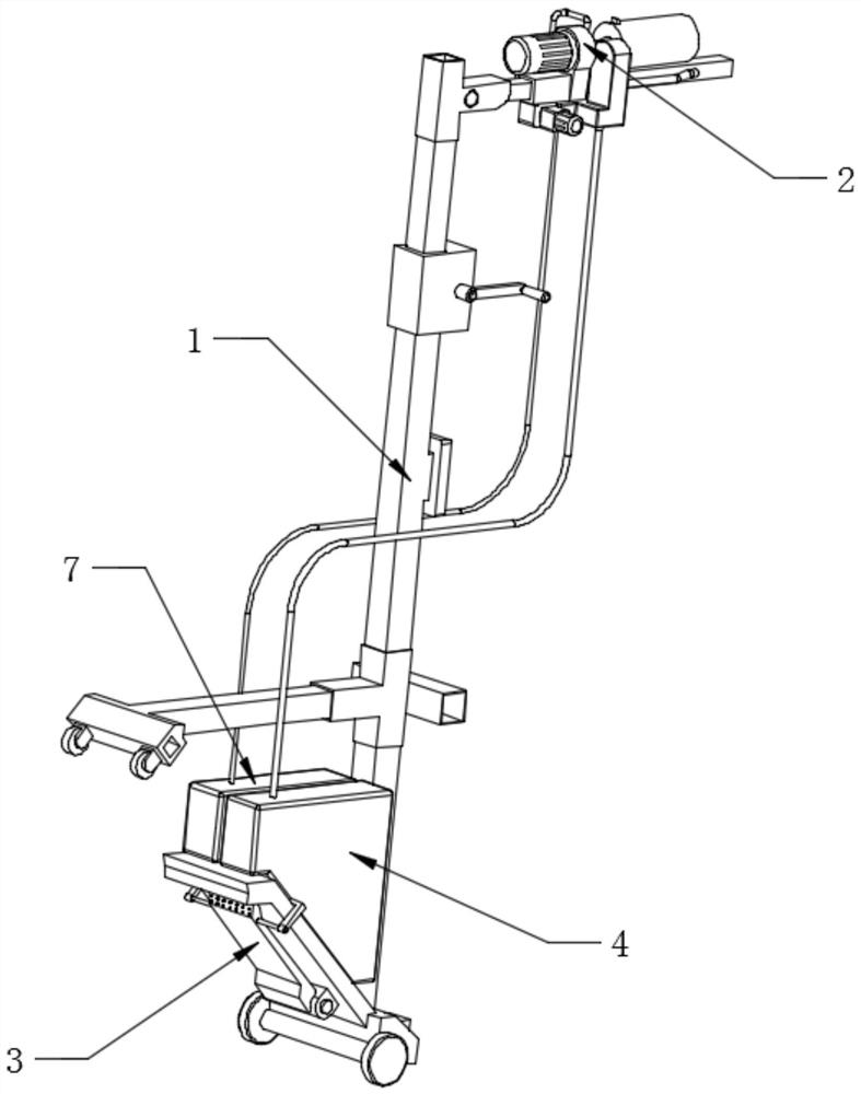
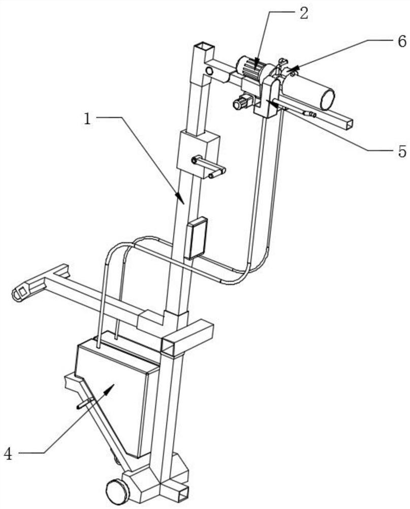
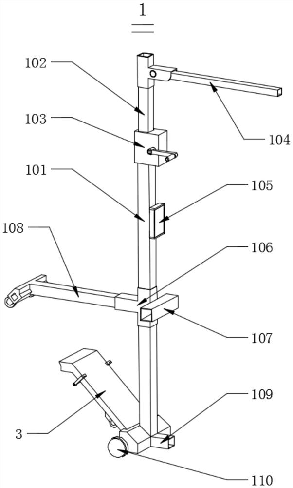
[0036] Please also refer to Figure 1-8 , figure 1 It is a schematic diagram of a rear-view three-dimensional structure in an embodiment of the present invention, figure 2 for figure 1 The front view three-dimensional structure schematic diagram shown in the embodiment, image 3 for figure 1 The three-dimensional schematic diagram of the ejector rod assembly shown in the embodiment, Figure 4 for figure 1 The three-dimensional s...


PUM


Abstract

The invention discloses a drilling device for building construction, comprising an ejector rod assembly, a drilling assembly, a bottom support structure, a linkage dust collecting device and a linkage water injection device, wherein the drilling assembly is movably installed on the top of the ejector rod assembly, The bottom support structure is fixedly installed on the bottom end of the ejector rod assembly, the linked dust suction device is fixedly installed on one side of the drilling assembly, and the linked water injection device is fixedly installed on the other side of the drilling assembly. On the one hand, the invention can ensure the straight movement of the drilling rig during the drilling process, and the ejector rod assembly is easy to move and has multiple functions. When drilling, the ejector rod assembly can be more stable, avoid accidental deviation, and effectively scrape In addition to the burrs at the hole ends and without destroying the existing hole pattern, it can also automatically realize the work of vacuuming and water filling, and does not need to use additional power devices, thereby reducing the energy consumption of the total device.

Description

technical field [0001] The invention relates to the technical field of drilling devices, in particular to a drilling device for building construction. Background technique [0002] The principle of the drilling device is that the motor rotor of the electromagnetic rotary or electromagnetic reciprocating small-capacity motor performs magnetic field cutting and work operation, and the working device is driven by the transmission mechanism to drive the gear to increase the power of the drill bit, so that the drill bit scrapes the surface of the object. It is widely used in the reinforcement of building beams, slabs, columns, walls, etc., decoration, wall installation, brackets, railings, billboards, outdoor units of air conditioners, guide rails, satellite receiver elevators, steel structure workshops, etc. [0003] However, the existing construction drilling device has the following defects: [0004] (1) Most of the existing construction drilling devices need to manually cont...

Claims


Application Information

Patent Timeline
Patent Type & Authority Patents(China)
IPC IPC(8): B23B45/02B23B45/14B23B51/08B23Q11/00
CPCB23B45/02B23B45/003B23B51/08B23Q11/0046B25H1/0035B25H5/00
Inventor 于泉于荞玮范杰杰
Owner 于泉
Learn More