
A lens and lens antenna based on 3D printing

A 3D printing and lens technology, used in antennas, electrical components, etc., can solve the problems of high processing cost of Lunberg lenses, difficult to achieve industrialization, and difficult to achieve miniaturization, and achieve high practicability, high design complexity, and high processing. low cost effect

Active Publication Date: 2019-01-04
XIDIAN UNIV
View PDF14 Cites 9 Cited by
  • Summary
  • Abstract
  • Description
  • Claims
  • Application Information

AI Technical Summary

Problems solved by technology

[0005] The present invention provides a lens and lens antenna based on 3D printing, which is used to solve the problem of the high processing cost and long processing cycle of the Lunberg lens in the prior art, which makes it difficult to realize industrialization; has high requirements for processing accuracy and design complexity. High; the technical problem of being difficult to realize miniaturization has achieved the technical effect of reducing production difficulty, facilitating production, low processing cost and high practicability

Method used


Image

  • A lens and lens antenna based on 3D printing
  • A lens and lens antenna based on 3D printing
  • A lens and lens antenna based on 3D printing

Examples


Embodiment 1

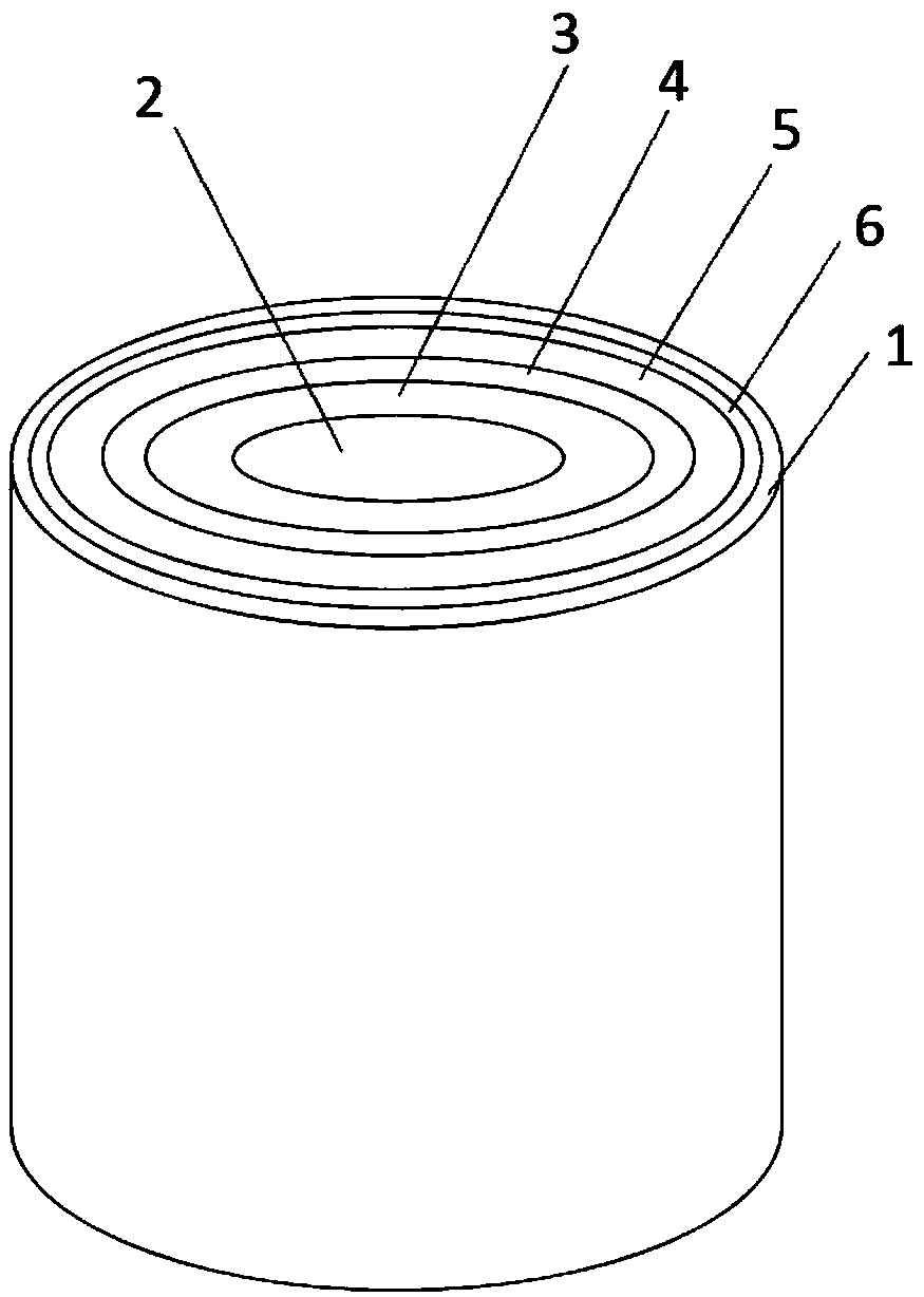
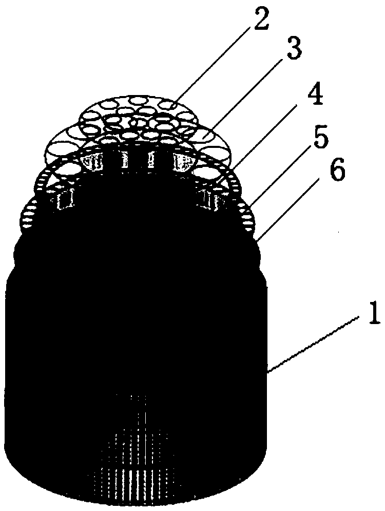
[0031] figure 1 It is a schematic structural diagram of a lens based on 3D printing in an embodiment of the present invention. like figure 1 As shown, the lens includes:

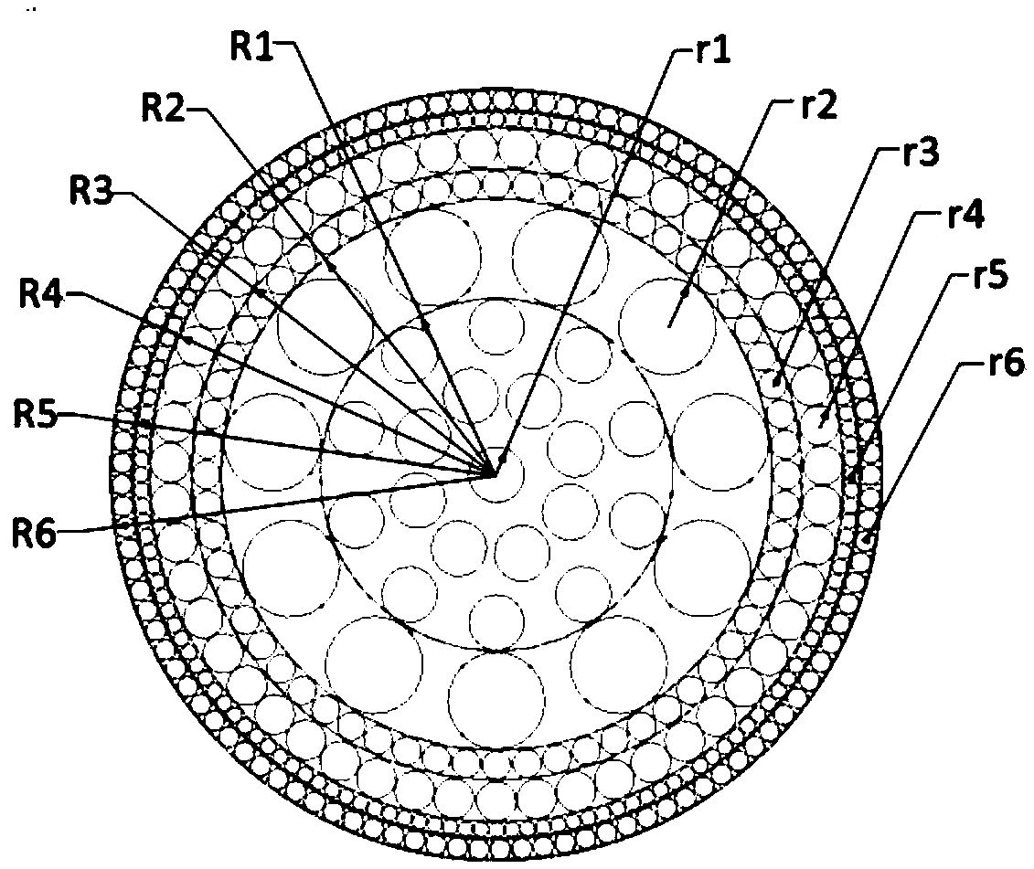
[0032]The cylindrical body 2 has a first radius and a first equivalent dielectric constant, wherein the cylindrical body 2 has a plurality of first through holes uniformly distributed through the upper and lower surfaces.

[0033] Further, the range of the first radius is 15-17mm; the first equivalent dielectric constant is 1.95; the radius of the first through hole is 2.5mm.

[0034] Specifically, the shape of the central cylindrical area 2 is a cylindrical structure, located at the center of the lens, and the central cylindrical area 2 and the lens have the same midline axis, and the central cylindrical area 2 The range of the first radius is 15-17mm. In this embodiment, the first radius R1=16mm is preferred, and the equivalent dielectric constant is 1.95. Wherein, the material of the central cylindrica...

Embodiment 2

[0051] An embodiment of the present invention also provides a lens antenna, including a feed antenna and the aforementioned lens, wherein the feed antenna is arranged parallel to the axis of the lens.

[0052] Specifically, place the feed antenna parallel to the axis of the lens antenna, take the antenna radiation surface at a distance of 44mm from the center of the lens, and use CST simulation software to perform simulation as an example. The simulation results show that the lens antenna has a greater impact on the feed antenna The effect of beam convergence is very obvious, and the maximum gain is increased by 10 dB. like Figure 5 As shown, it can be seen that its 3dB lobe width is 7.4°, such as Image 6 As shown, it can be seen that its 3dB lobe width is 10.6°, and the above results further show that the loaded lens antenna has a strong converging effect on the pattern of the feed antenna. Since the present invention has no special requirements for the feed antenna, as l...


PUM

PropertyMeasurementUnit
Outer radiusaaaaaaaaaa
Radiusaaaaaaaaaa
Heightaaaaaaaaaa

Abstract

The invention discloses a lens and a lens antenna based on 3D printing, belonging to the technical field of lens antenna. Through a cylindrical body, the cylindrical body has a first radius and a first equivalent dielectric constant, wherein, the cylindrical body is uniformly distributed with a plurality of first through holes penetrating the upper and lower surfaces; M hollow cylindrical structures, M hollow cylindrical structures are sequentially sleeved outside the cylindrical body, and all are concentrically arranged with the cylindrical body, wherein M is a positive integer, each hollow cylindrical structure is uniformly distributed with a plurality of through holes penetrating the upper and lower surfaces, and any two through holes are not connected with each other; A hollow cylindrical housing having a preset height. The invention solves the problems of high processing cost, long processing period and high design complexity of the Lombo lens in the prior art. The technical problem that it is difficult to realize miniaturization has reached the technical effect of reducing production difficulty, facilitating manufacture, low processing cost and high practicability.

Description

technical field [0001] The invention relates to the technical field of lens antennas, in particular to a 3D printing-based lens and a lens antenna. Background technique [0002] A lens antenna is an antenna that can convert a point or line source spherical or cylindrical wave into a plane wave through electromagnetic waves to obtain a pencil-shaped, fan-shaped or other shaped beam. By rationally designing the shape of the lens surface and the refractive index n, the phase velocity of the electromagnetic wave is adjusted to obtain a plane wavefront on the radiation aperture. Lens antennas have absorbed many optical information engineering technologies, and thus have been widely used in communication and military fields, and have attracted more attention from people in the industry. According to the theory of geometric optics, the spherical wave radiated by the point light source at the focal point of the lens is refracted and converged by the lens, and finally forms a plane ...

Claims


Application Information

Patent Timeline
IPC IPC(8): H01Q19/06H01Q15/02H01Q15/08
CPCH01Q15/02H01Q15/08H01Q19/06
Inventor 侯建强蒋沅臻
Owner XIDIAN UNIV
Learn More