
Hall sensor

A Hall sensor and temperature sensor technology, applied in the sensor field, can solve the problems of amplifier signal distortion, affecting the accuracy of the Hall sensor, and being susceptible to external electromagnetic interference, so as to improve the measurement accuracy and avoid electromagnetic interference.

Inactive Publication Date: 2019-01-04
上海岱梭动力科技有限公司
View PDF9 Cites 7 Cited by
  • Summary
  • Abstract
  • Description
  • Claims
  • Application Information

AI Technical Summary

Problems solved by technology

However, the Hall sensor works in a relatively complex electromagnetic environment. The induced voltage signal generated by the Hall plate induced by the magnetic field change is susceptible to external electromagnetic interference, resulting in distortion of the signal output to the amplifier and affecting the accuracy of the Hall sensor.

Method used


Image

  • Hall sensor
  • Hall sensor
  • Hall sensor

Examples


Embodiment Construction

[0030] The following will clearly and completely describe the technical solutions in the embodiments of the present invention with reference to the accompanying drawings in the embodiments of the present invention. Obviously, the described embodiments are only part of the embodiments of the present invention, not all of them. Based on the embodiments of the present invention, all other embodiments obtained by persons of ordinary skill in the art without creative efforts fall within the protection scope of the present invention.

[0031] It should be noted that all directional indications (such as up, down, left, right, front, back...) in the embodiments of the present invention are only used to explain the relationship between the components in a certain posture (as shown in the accompanying drawings). Relative positional relationship, movement conditions, etc., if the specific posture changes, the directional indication will also change accordingly.

[0032] In addition, the ...


PUM


Abstract

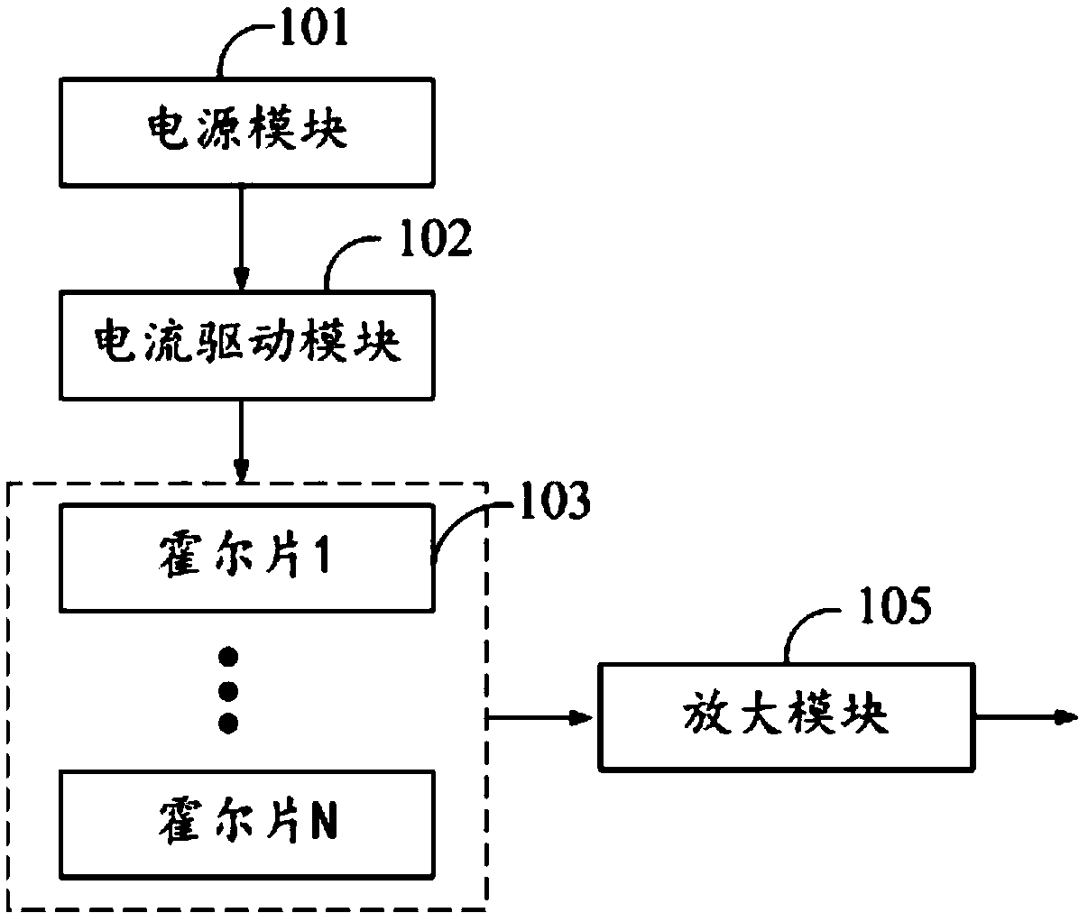
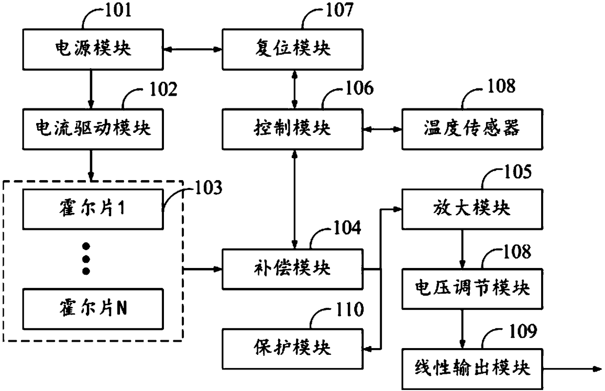
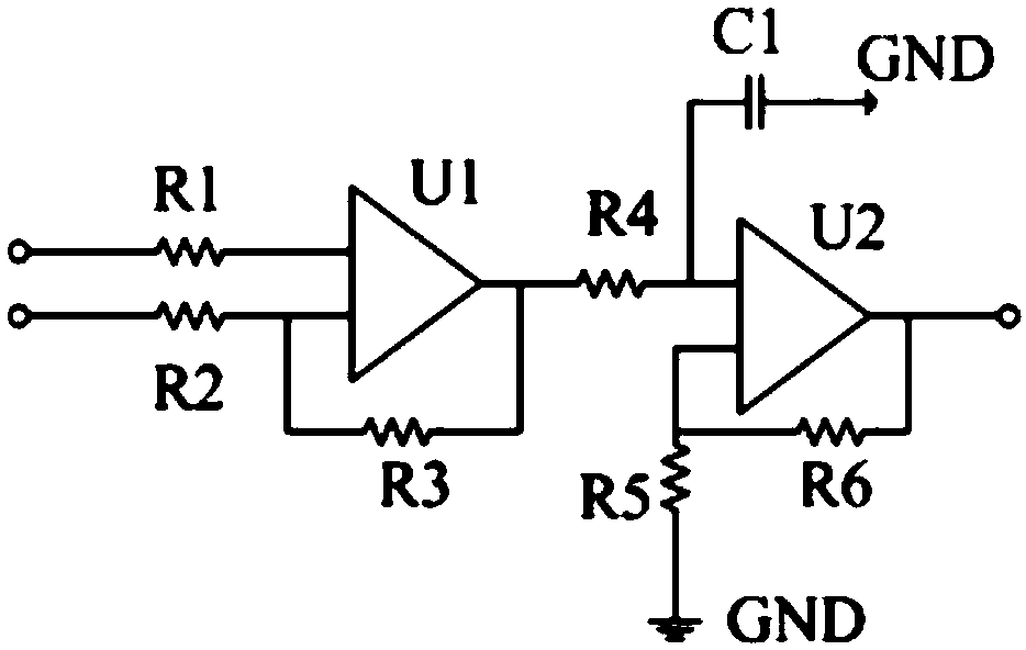
The invention discloses a Hall sensor. The Hall sensor comprises a power supply module, a current driving module, differential pairs formed by N Hall sheets and a signal amplification module. The power supply module is used for supplying power to all the modules in the Hall sensor. The current driving module is used for supplying constant driving current to the Hall sheets. The Hall plates are used for generating an induced voltage signal proportional to the magnetic induction intensity when a magnetic field perpendicular to the Hall plates is induced and forming the differential pairs for eliminating the external common-mode interference. The amplification module is used for amplifying the power of the induced voltage signal outputted by the Hall plates and outputting the amplified signal. According to the technical scheme, the electromagnetic interference to the signal from the outside of the sensor in the measurement process can be effectively avoided and the measurement accuracy ofthe Hall sensor can be improved.

Description

technical field [0001] The invention relates to the technical field of sensors, in particular to a Hall sensor. Background technique [0002] A Hall sensor is a transducer that converts a changing magnetic field into a change in output voltage. Hall sensors can be used to measure magnetic fields and, in addition, physical quantities that generate and influence magnetic fields, for example in proximity switches, position measurement, rotational speed measurement and current measurement devices. [0003] For example, the Hall sensor detects the current, usually the conductor to be detected is introduced into the sensor, and the current flowing through the conductor is obtained by measuring the magnetic field generated by the conductor. However, the Hall sensor works in a relatively complex electromagnetic environment. The induced voltage signal generated by the Hall plate after the magnetic field changes is easily subject to external electromagnetic interference, which leads ...

Claims


Application Information

Patent Timeline
Patent Type & Authority Applications(China)
IPC IPC(8): G01R33/07G01D5/14G01D3/028
CPCG01D3/028G01D5/14G01R33/007G01R33/072
Inventor 余执钧方朝曦金荣华
Owner 上海岱梭动力科技有限公司
Learn More