Laser detection device and laser detection control method

A technology of laser detection and controller, which is applied in measuring devices, optical instrument testing, testing optical properties, etc., can solve the problems of low efficiency and achieve the effect of improving efficiency and reducing production costs

Inactive Publication Date: 2019-01-04
SHENZHEN JPT OPTO ELECTRONICS CO LTD
View PDF6 Cites 2 Cited by
  • Summary
  • Abstract
  • Description
  • Claims
  • Application Information

AI Technical Summary

Problems solved by technology

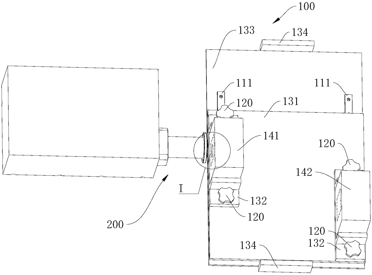
[0003] In order to overcome the deficiencies in the above-mentioned prior art, the present invention provides a laser detection device and a laser detection control method, which can simplify the operation of adjusting the position of the device and help to improve the detection efficiency, thereby improving the prior art due to the need for The technical problem of low efficiency caused by the position adjustment of the whole device

Method used


Image

  • Laser detection device and laser detection control method
  • Laser detection device and laser detection control method
  • Laser detection device and laser detection control method

Examples


Embodiment Construction

[0032] The following will clearly and completely describe the technical solutions in the embodiments of the present invention with reference to the drawings in the embodiments of the present invention. Apparently, the described embodiments are only some of the embodiments of the present invention, not all of them. The components of the embodiments of the invention generally described and illustrated in the figures herein may be arranged and designed in a variety of different configurations.

[0033] It should be noted that like numerals and letters denote similar items in the following figures, therefore, once an item is defined in one figure, it does not require further definition and explanation in subsequent figures.

[0034] In the description of the present invention, it should be noted that the orientations or positional relationships indicated by the terms "middle", "upper", "lower", "horizontal", "inner" and "outer" are based on those shown in the accompanying drawings...


PUM


Abstract

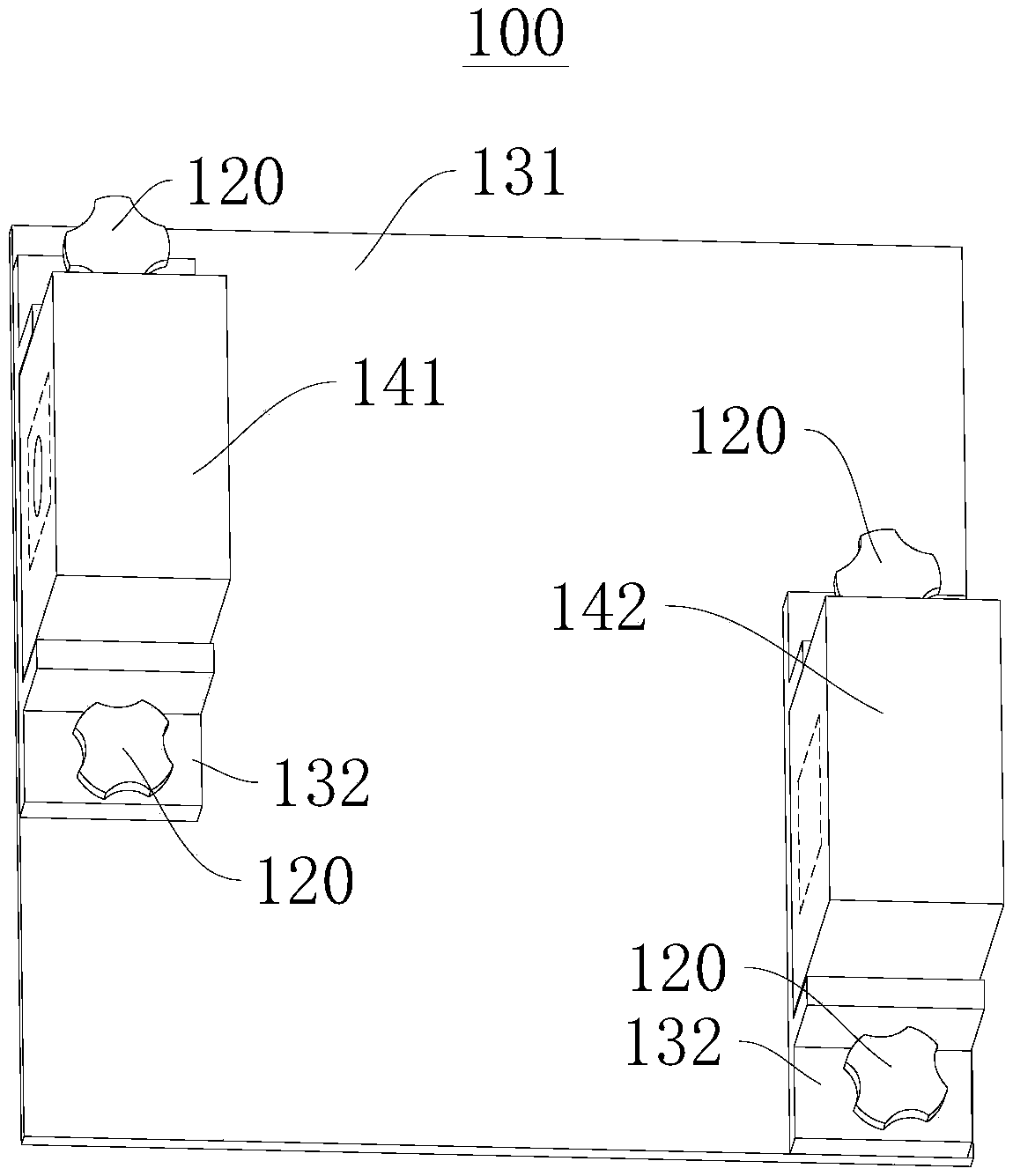
The present invention provides a laser detection device and a laser detection control method, and relates to the technical field of laser detection. The laser detection device comprises a position regulation module and a laser detection module, the position regulation module is connected with the laser detection module, and the position regulation module is configured to regulate the space position of the laser detection module to allow a laser emitted by a laser to be measured to be irradiated in a detection area corresponding to the laser detection module. The position regulation module is employed to achieve the regulation of the space position of the laser detection module with no need for increasing processing for the area of the detection area, and to allow the laser to be irradiatedin a corresponding detection area so as to reduce the manufacturing cost of the device. The position regulation module is employed to regulate the space position of the laser detection module with noneed for position regulation of the whole laser detection device so as to improve the efficiency of the position regulation and facilitate improvement of the efficiency of the laser detection.

Description

technical field [0001] The invention relates to the technical field of laser detection, in particular to a laser detection device and a laser detection control method. Background technique [0002] In the application field of solid-state laser processing, it is usually necessary to detect the corresponding parameters (such as output power and light spot) of the manufactured laser. Because there are many types of lasers that need to be detected, and the heights of each type of laser are different, if all types of lasers are placed at the same position, the position where the laser light emitted by each laser is irradiated on the detection device is also different. To realize the detection of the corresponding parameters of the laser, it is necessary to irradiate the emitted laser light in the corresponding detection area. In the prior art, limited by the structure of the detection device, the detection area is not easy to adjust. A detection device is usually only suitable f...

Claims


Application Information

Patent Timeline
Patent Type & Authority Applications(China)
IPC IPC(8): G01M11/02
CPCG01M11/00
Inventor 黄杰生徐罗洋任戬
Owner SHENZHEN JPT OPTO ELECTRONICS CO LTD
Why Eureka
Try Eureka