
Novel one-touch image measurement device

A video measurement and one-button technology, which is applied in the field of new one-button video measurement equipment, can solve the problems that the light of the object cannot be perpendicular to the surface, it is inconvenient to observe and analyze the detection data, and it is impossible to adjust the angle of the display screen.

Inactive Publication Date: 2019-01-04
深圳市天航光学设备有限公司
View PDF6 Cites 0 Cited by
  • Summary
  • Abstract
  • Description
  • Claims
  • Application Information

AI Technical Summary

Problems solved by technology

[0003] At present, the measurement field of view of one-button measuring equipment on the market is generally not larger than 130mmX130mm, which cannot meet the detection of products with a larger range.
It uses a telecentric parallel light source. When the product to be detected has a radian, the radian changes the direction of the light, so that the light of the object cannot be perpendicular to the surface, and the detected data has a large error
And most of them use ordinary parallel light sources. When the light transmittance of the product to be detected is strong (such as thin glass), due to the strong light transmittance, the edge of the product to be detected is blurred, and the CCD (industrial camera) cannot capture a clear image. Image, the detected data has a large error, and the one-button measuring equipment currently on the market has a fixed display screen, and the angle of the display screen cannot be adjusted, which is not convenient for the inspection personnel to observe and analyze the detection data

Method used


Image

  • Novel one-touch image measurement device
  • Novel one-touch image measurement device
  • Novel one-touch image measurement device

Examples


no. 1 example

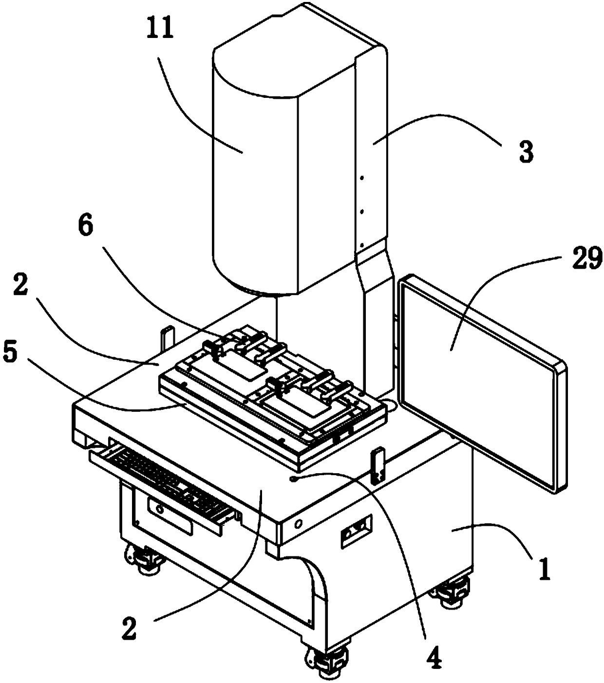
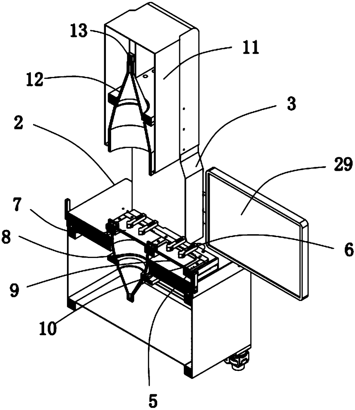
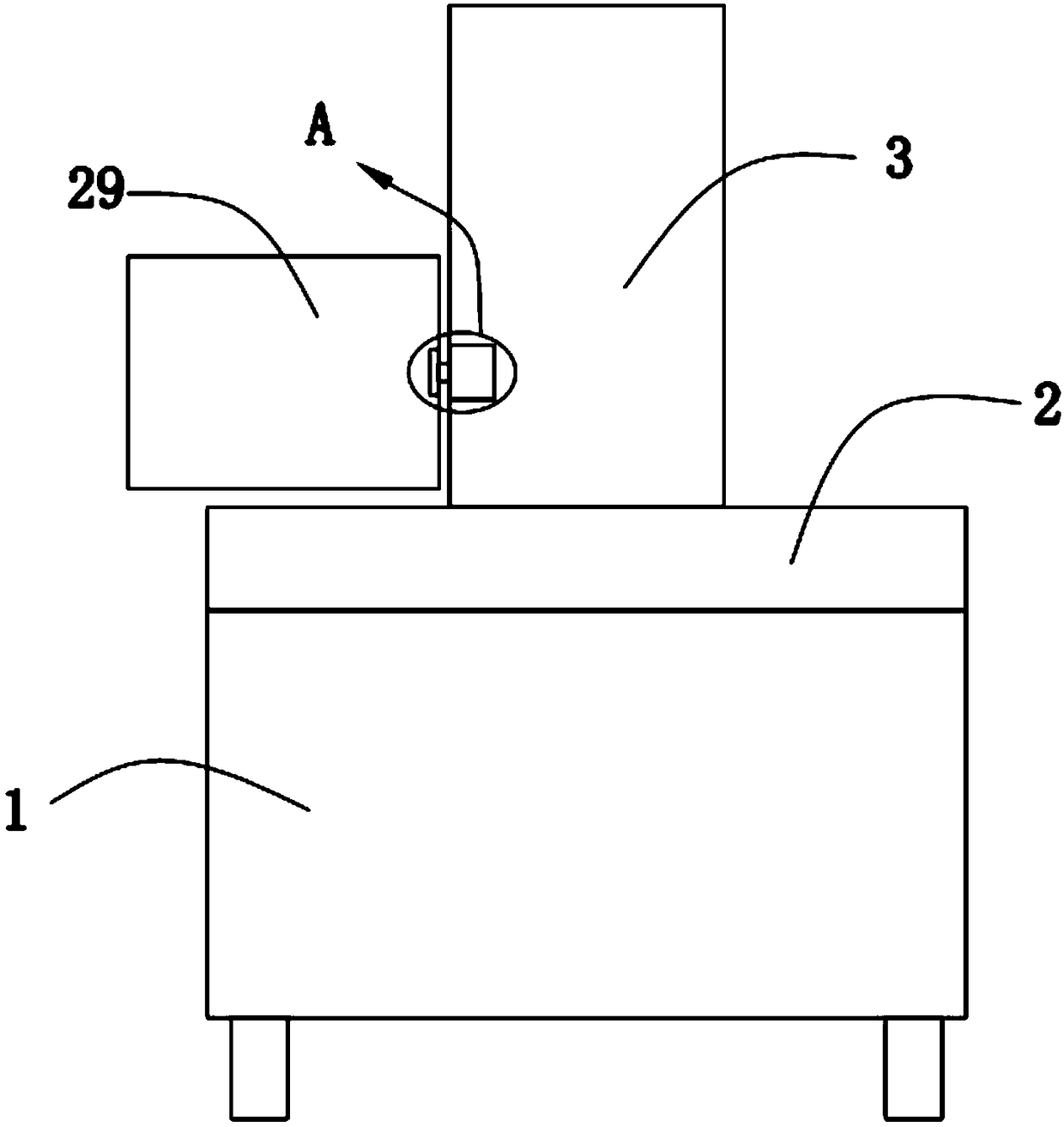
[0030] The invention proposes a new type of one-button image measuring equipment

[0031] Please refer to Figure 1-5 , in an embodiment of the present invention, a box body 1 is provided with a host computer and a pull-out keyboard; a marble platform 2, and the marble platform 2 is fixedly mounted on the top of the box body 1; a marble column 3, a marble The column 3 is fixedly installed on the top of the marble platform 2; the photosensitive sensor 4 is fixedly installed on the top of the marble platform 2; the bottom moving slide rail 10 is fixedly installed on the top of the marble platform 2 Movable marble platform 5, movable marble platform 5 is slidably installed on the top of bottom slide rail 10; Positioning jig 6, positioning jig 6 is positioned at the top of movable marble platform 5; Detection platform 7, detection platform 7 is fixedly installed on the movable The top of the marble 5; the telecentric parallel light source 8, the telecentric parallel light source ...

no. 2 example

[0035] see Figure 3-5 The difference between this embodiment and the first embodiment is that when the angle of the display 29 needs to be adjusted, the first handle is used to keep the rotating rod 20 from rotating, and then the second handle is turned, and the second handle drives the screw rod 28 to rotate in the threaded hole 27 , the screw rod 28 drives the second trapezoidal block 26 to move away from the direction of the rotating groove 15. Under the tension of the spring, the spring drives the two first trapezoidal blocks 23 to approach each other, so that the two first trapezoidal blocks 23 are all in contact with the rubber The ring 24 is out of contact, and then the rotating rod 20 is rotated, the rotating rod 20 drives the second bevel gear 21 to rotate, the second bevel gear 21 drives the first bevel gear 18 to rotate, and the first bevel gear 18 drives the connecting block 16 to rotate, The connecting block 16 drives the second support block 17 to rotate, and th...


PUM


Abstract

The present invention provides a novel one-touch image measurement device. The one-touch image measurement device comprises: a box body; a marble platform fixedly installed at the top portion of the box body; a marble stand column fixedly installed at the top portion of the marble platform; a light sensation inductor fixedly installed at the top portion of the marble platform; a bottom mobile slide rail fixedly installed at the top portion of the marble platform; a movable marble platform slidingly installed at the top portion of the bottom mobile slide rail; and a location tool located at thetop portion of the movable marble platform. The novel one-touch image measurement device is high in detection efficiency, large in detection measuring range and low in requirement for the detection products, and can perform angle regulation for the display screen.

Description

technical field [0001] The invention relates to the technical field of image measuring equipment, in particular to a novel one-button image measuring equipment. Background technique [0002] In recent years, with the development of industrial technology, people have higher and higher requirements for the production of products, and put forward higher requirements for the size and surface smoothness of products. Image measuring equipment has been widely used in industrial production and testing because it can directly detect samples. [0003] At present, the measurement field of view of one-button measuring equipment on the market is generally not larger than 130mmX130mm, which cannot meet the detection of products with a larger range. It uses a telecentric parallel light source. When the product to be detected has a radian, the radian changes the direction of the light, so that the object light cannot be perpendicular to the surface, and the detected data has a large error....

Claims


Application Information

Patent Timeline
Patent Type & Authority Applications(China)
IPC IPC(8): G01B11/00F16M11/04F16M11/10
CPCF16M11/04F16M11/10G01B11/00
Inventor 雷修权
Owner 深圳市天航光学设备有限公司
Learn More