Eureka AIR delivers breakthrough ideas for toughest innovation challenges, trusted by R&D personnel around the world.

Medium-frequency electric furnace slag extractor

A technology of intermediate frequency electric furnace and slag removal machine, which is applied in the direction of furnace, furnace components, charge control, etc., which can solve the problems of scum and alloy melt flying out, poor scum clamping effect, and insufficient slag removal, etc., to achieve closed Good performance, improved accuracy and slag removal efficiency, and large slag removal capacity

Inactive Publication Date: 2019-01-04
宁国市挚友合金钢材料有限公司
View PDF7 Cites 4 Cited by
  • Summary
  • Abstract
  • Description
  • Claims
  • Application Information

AI Technical Summary

Problems solved by technology

However, the scissor gripper has a special shape and a relatively large size, and there will be a dead angle when working. When facing the cylindrical furnace body of the electric furnace, it can only grab the scum in the center of the furnace body. scum, often difficult to remove
In addition, when the gripper grabs small scum, a small amount of scum and molten alloy will fly out from the upper part of the gripper during the movement of the boom to the slag removal system, which will also bring certain safety hazards
[0005] Invention Patent Publication No. CN107916318A discloses a slag removal machine. This slag removal machine replaces the slag removal gripper of the traditional slag removal system with two slag removal claws connected by a rotating shaft, and the slag removal Gather and step up to remove the slag. This method of slag removal is very suitable for the intermediate frequency electric furnace of the circular furnace body, and can reduce the working dead angle. safety risk and insufficient slag removal

Method used


Image

  • Medium-frequency electric furnace slag extractor
  • Medium-frequency electric furnace slag extractor
  • Medium-frequency electric furnace slag extractor

Examples


Embodiment Construction

[0034]In order to make the purpose, technical solutions and advantages of the embodiments of the present invention more clear, the technical solutions in the embodiments of the present invention will be clearly and completely described below in conjunction with the drawings in the embodiments of the present invention.

[0035] In the description of the present invention, it should be noted that unless otherwise specified, the meaning of "plurality" is two or more; the terms "upper", "lower", "left", "right", "inner ", "outside", "front end", "rear end", "top", "bottom" and other indicated orientations or positional relationships are based on the orientations or positional relationships shown in the drawings, and are only for the convenience of describing the present invention and simplifying the Describes, but does not indicate or imply that the device or element referred to must have a specific orientation, be constructed in a specific orientation, and operate in a specific or...


PUM


Abstract

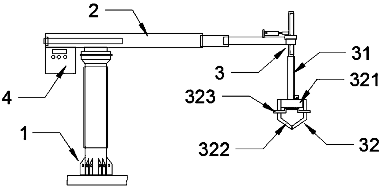
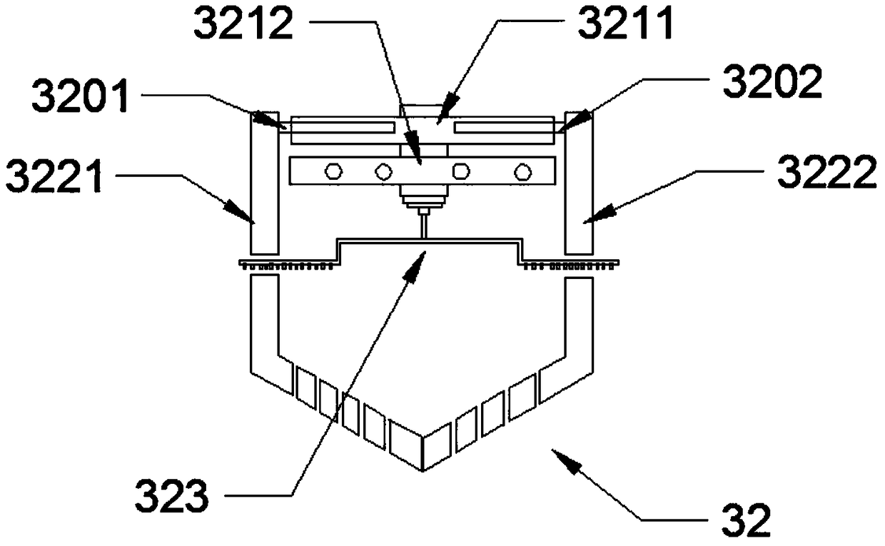
The invention belongs to the technical field of high-temperature metallurgy equipment, and particularly relates to a medium-frequency electric furnace slag extractor. The medium-frequency electric furnace slag extractor comprises a vertical supporting seat, a cross arm connected to the top end of the supporting seat and a slag fishing system connected to the front end of the cross arm, wherein theslag fishing system comprises a slag fishing arm capable of ascending and descending in the vertical direction, and the lower end of the slag fishing arm is connected with a slag fishing cage. The slag fishing cage comprises a control seat, slag fishing claw teeth and a slag gathering stirrer, wherein the control seat comprises an upper part and a lower part, the first control seat and the secondcontrol seat are respectively connected with the four slag fishing claw teeth through four groups of telescopic air cylinders, the slag gathering stirrer can ascend and descend, a slag gathering combis arranged below a stirring rod of the slag gathering stirrer, and the slag gathering comb gathers dross at the edge of the furnace body to the center of the furnace body through the comb teeth. Themedium-frequency electric furnace slag extractor is high in slag removal efficiency, no dead angle exists during operation, the safety hazards of flying slag and slag falling do not exist, and the medium-frequency electric furnace slag extractor is very safe and efficient.

Description

technical field [0001] The invention belongs to the technical field of high-temperature metallurgical equipment, and in particular relates to a slag scraper for an intermediate frequency electric furnace. Background technique [0002] The intermediate frequency electric furnace is a new type of high temperature furnace, which uses the eddy current effect of the alternating current magnetic field for metal melting or heat treatment. The intermediate frequency electric furnace can convert the power frequency 50HZ AC power into an intermediate frequency (above 300HZ to 20K HZ) power supply device, convert the three-phase power frequency AC power into DC power after rectification, and then convert the DC power into an adjustable intermediate frequency current, which is supplied by capacitors and The medium-frequency alternating current flowing in the induction coil generates high-density magnetic force lines in the induction coil, and cuts the metal material contained in the ind...

Claims


Application Information

Patent Timeline
IPC IPC(8): F27D3/15
CPCF27D3/1545
Inventor 王青云
Owner 宁国市挚友合金钢材料有限公司
Why Eureka
Eureka Blog
Learn More