
Design method of magnetic type planet gear

A design method and planetary gear transmission technology, applied in belt/chain/gear, mechanical equipment, transmission, etc., can solve problems such as damage to transmission, plastic deformation of gear tooth profile shape, gear tooth breakage, etc., to eliminate noise and vibration, increase torque density, increase the effect of transmission torque

Inactive Publication Date: 2019-01-04
UNIV OF JINAN
View PDF9 Cites 4 Cited by
  • Summary
  • Abstract
  • Description
  • Claims
  • Application Information

AI Technical Summary

Problems solved by technology

Although the technology of mechanical gear transmission is becoming more and more mature, but the machinery is a contact meshing transmission, there must be defects that are difficult to eliminate in traditional mechanical transmission: First, the transmission between ordinary gears relies on the contact between the tooth surfaces of the two gears for rigid meshing. The high temperature causes the gear teeth to bond together, resulting in tooth surface gluing, and even destroys the plastic deformation of the tooth profile shape of the gear, and the breakage of the gear teeth, which leads to the failure or serious damage of the mechanism during the transmission process.
[0013] The most important thing is that the magnetic suction planetary gear has strong overload capacity. Since the transmission torque of the mechanical gear is carried out through the mechanical direct contact and meshing between the gear teeth, when the load is too high, if there is no corresponding protection measure, it is easy to The gear teeth are broken and plastically deformed and the transmission device is damaged; when corresponding protection measures are taken, the transmission mechanism will be more complicated and difficult to operate and maintain

Method used


Image

  • Design method of magnetic type planet gear
  • Design method of magnetic type planet gear
  • Design method of magnetic type planet gear

Examples


Embodiment Construction

[0042] In order to clearly illustrate the technical features of the present solution, the present invention will be described in detail below through specific implementation methods and in conjunction with the accompanying drawings.

[0043] It should be noted that components illustrated in the figures are not necessarily drawn to scale. Descriptions of well-known components and techniques are omitted herein to avoid unnecessarily limiting the present invention.

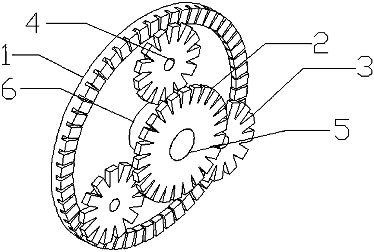
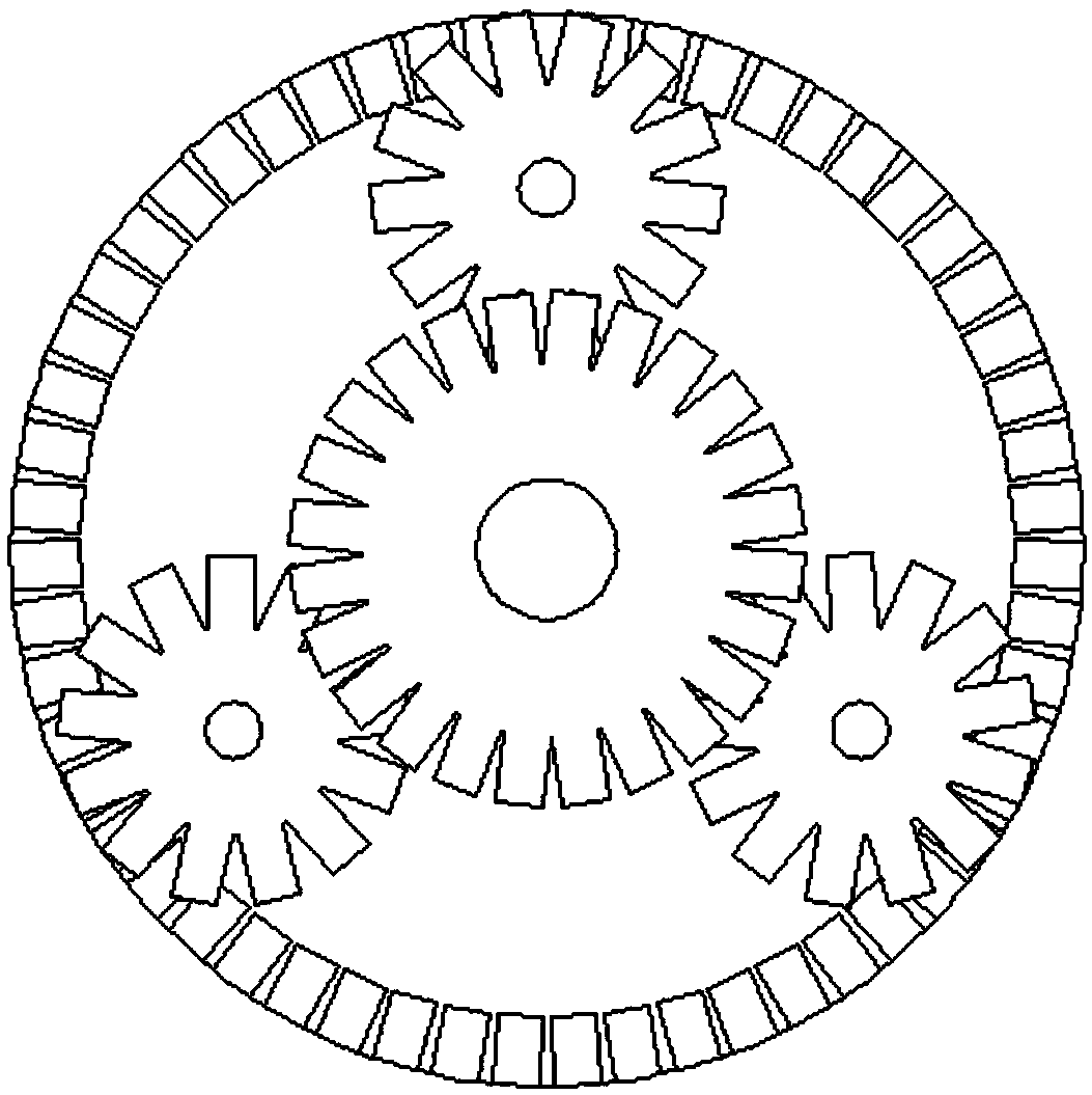
[0044] Such as Figure 1-3 As shown, a design method of a magnetic planetary gear, the design includes a magnetic sun gear 1, a magnetic center gear 2, and a magnetic planetary gear 3; the magnetic sun gear 1 and the magnetic planetary gear 3 are axially magnetically coupled, and the magnetic The planetary wheel 3 and the magnetic center wheel 2 are axially magnetically coupled, and the magnetic poles of the magnetic gear blocks on the axial coupling surface of the magnetic center wheel are distributed in N, S, N, S, ...


PUM


Abstract

The invention provides a design method of a magnetic type planet gear mechanism. The design method of the magnetic type planet gear mechanism is used for solving the technical problem of magnetic typeplanet gear transmission. The magnetic type planet gear mechanism comprises a magnetic sun gear, a magnetic center gear, a magnetic planet gear, a small transmission shaft, a large transmission shaftand a sleeve, the center gear and the magnetic planet gear are axially connected in parallel, and the magnetic sun gear is correspondingly in axial series connection with the magnetic center gear andthe magnetic planet gear; magnetic poles of axially opposite magnetic tooth blocks are different, so that axial attraction is generated, off-axial opposite magnetic poles are the same, so that axialmutex force is generated, automatic core adjustment is realized, and an incomplete axial coupling area is formed; and the acting force between the magnetic tooth blocks is compensated mutually throughthe magnitude of the attraction and the mutex force, and stable torque transmission is formed. The design method of the magnetic type planet gear mechanism has the beneficial effects that noise and vibration generated by mechanical meshing are removed fundamentally, and the reliability of a transmission system is increased; the torque density is high and a fixed peak value is achieved, the returndifference of transmission is decreased, automatic decoupling is carried out during overload, transmission connection is cut off, and a prime motor is protected.

Description

technical field [0001] The invention relates to the technical field of magnetic attraction transmission methods, in particular to a design method of a magnetic attraction type planetary gear mechanism. Background technique [0002] The characteristics of traditional mechanical gear transmission include fixed transmission ratio, high transmission efficiency, small volume range, high reliability and compact transmission structure. [0003] Among them, the advantages of the mechanical planetary gear include a larger transmission ratio, a more compact transmission structure, and at the same time, it also has overload capacity, reliability and meshing degree. [0004] Therefore, various forms of gear transmission mechanisms are widely used in various fields, including textile industry, metallurgy and mining, design of defense technology parts, military industry, new energy direction and ship transmission technology. [0005] The gear reducer or variable speed transmission mechan...

Claims


Application Information

Patent Timeline
IPC IPC(8): F16H49/00
CPCF16H49/00
Inventor 余文涛王成
Owner UNIV OF JINAN
Learn More