Corner telescopic structure
A telescopic structure and corner technology, which is applied in building construction, on-site preparation of building components, formwork/template/work frame, etc., can solve the problem of weakening the support effect of reinforcing ribs, and achieve low processing cost, convenient connection and The effect of disassembly and meeting the connection requirements
- Summary
- Abstract
- Description
- Claims
- Application Information
AI Technical Summary
Problems solved by technology
Method used
Image
Examples
Embodiment 1
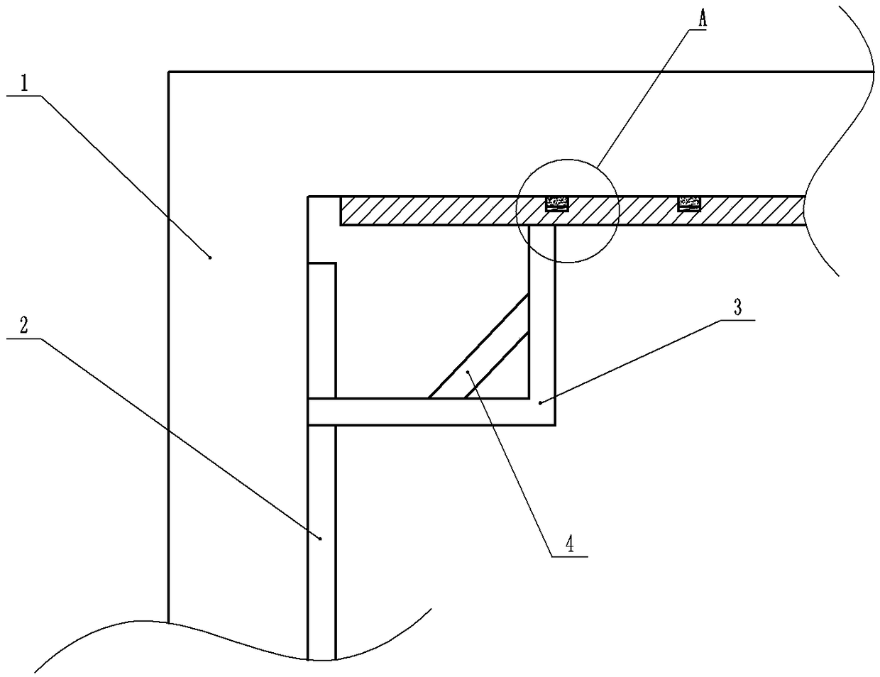
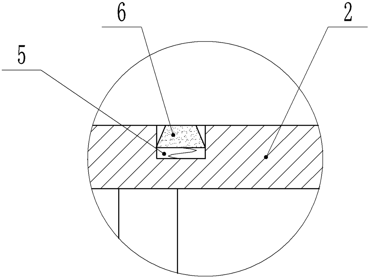
[0031] As attached figure 1 And figure 2 Shown: a corner telescopic structure, including a slide rail installed on the inner side of the aluminum template 1, the slide rail is perpendicular to the connecting edge of the two aluminum templates 1, the slide rail is slidably connected with a reinforcement rib 2, and the reinforcement rib 2 runs along it. A number of grooves 5 are provided in the axial direction, and a support block 6 is slidably connected in the groove 5. The cross section of the support block 6 is in an isosceles trapezoid shape.
[0032] A back rib 3 is connected between the two reinforcing ribs 2, and the back rib 3 is made of steel. The back rib 3 is L-shaped, and the back rib 3 includes an integrally formed transverse rib 10 and a vertical rib 11, a reinforcing rib 4 is fixed between the transverse rib 10 and the vertical rib 11, and three of the reinforcing rib 4, the transverse rib 10 and the vertical rib 11 are fixed. Form a right triangle. A U-shaped groo...
Embodiment 2
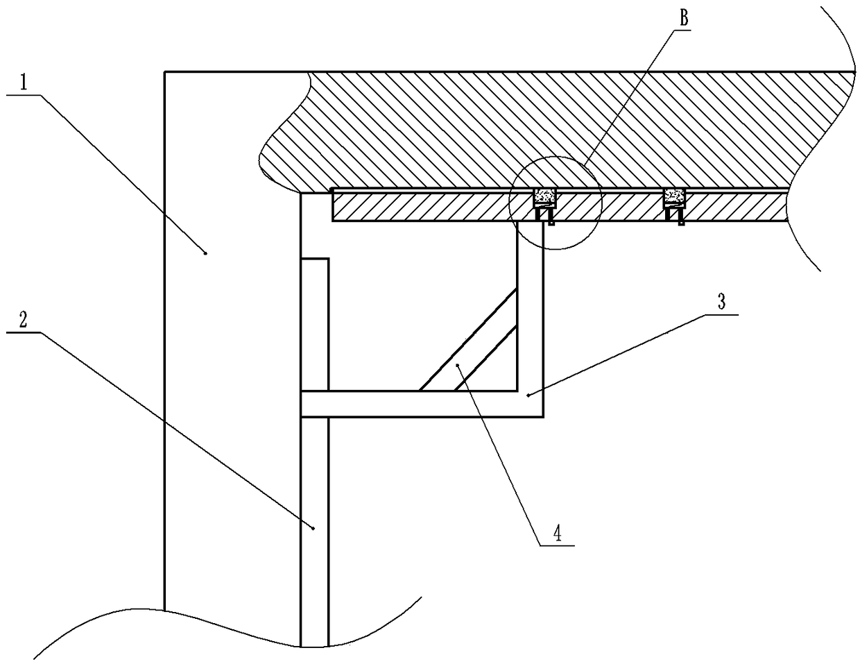
[0037] The difference between this embodiment and the first embodiment lies in: image 3 with Figure 4 As shown, there is a gap of 3-6 mm between the reinforcing rib 2 and the sliding rail. In this embodiment, 5 mm is selected. An electromagnet and a power supply for energizing the power supply magnet are fixed in the groove 5, and a magnetic block is fixed on the supporting block 6, and the electromagnet has a repulsive effect on the magnetic block after being energized. The cross section of the support block 6 is trapezoidal. The bottom of the groove 5 is provided with an air outlet 7 and a suction hole 8. The suction hole 8 is provided with a suction check valve. When the air pressure in the groove 5 decreases, the outside air passes through the suction The gas check valve enters the groove 5. The air outlet hole 7 is provided with an air outlet check valve. When the air pressure in the groove 5 increases, the air in the groove 5 is discharged through the air outlet check v...
Embodiment 3
[0044] The difference between this embodiment and the first embodiment lies in: Figure 5 with Image 6 As shown, the bottom of the U-shaped groove 18 is provided with a connecting hole 20. The connecting hole 20 is connected with an airbag 19 through a pin. That is, the lower end of the airbag 19 is glued with a pin. During installation, the pin is inserted into the connecting hole 20 to realize the airbag 19 in the U Fix in the groove 18. A clamping block 17 is slidably connected in the U-shaped groove 18, and the airbag 19 is arranged between the clamping block 17 and the U-shaped groove 18. The airbag 19 is provided with a vent hole, and a valve is provided in the vent hole.
[0045] An air tank 12 is fixed on both the horizontal rib 10 and the vertical rib 11, a sliding board is slidably connected to the air tank 12, a piston rod 13 is fixed on the sliding board, a spring is fixed between the sliding board and the bottom of the air tank 12, the air tank 12 is provided with...
PUM
 Abstract
Description
Claims
Application Information
 - R&D
- Intellectual Property
- Life Sciences
- Materials
- Tech Scout
- Unparalleled Data Quality
- Higher Quality Content
- 60% Fewer Hallucinations
Browse by: Latest US Patents, China's latest patents, Technical Efficacy Thesaurus, Application Domain, Technology Topic, Popular Technical Reports.
© 2025 PatSnap. All rights reserved.Legal|Privacy policy|Modern Slavery Act Transparency Statement|Sitemap|About US| Contact US: help@patsnap.com


