
A push sweeper

A sweeping machine and push-type technology, applied in cleaning methods, construction, road surface cleaning, etc., can solve problems such as cleaning inconvenience, and achieve the effect of preventing accidental opening, preventing misoperation, and locking reliably

Active Publication Date: 2020-04-14
长沙扬子工业设备有限公司
View PDF7 Cites 0 Cited by
  • Summary
  • Abstract
  • Description
  • Claims
  • Application Information

AI Technical Summary

Problems solved by technology

[0005] The purpose of the present invention is to provide a push-type sweeper, which solves the problem that in the existing push-type sweeper, the cleaned garbage needs to be taken out from the upper cover of the dust box, which is very inconvenient for cleaning.

Method used


Image

  • A push sweeper
  • A push sweeper
  • A push sweeper

Examples


Embodiment Construction

[0029] The embodiments of the present invention will be described in detail below with reference to the accompanying drawings, but the present invention can be implemented in many different ways defined and covered by the claims.

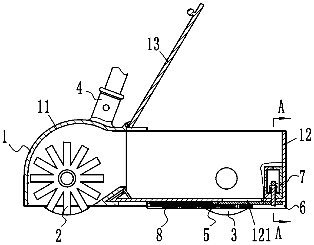
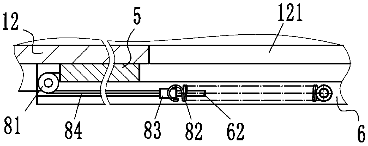
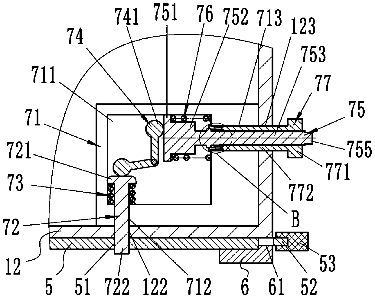
[0030] Refer below Figure 1 to Figure 7 The present invention is further described, as figure 1 The push-type sweeping machine shown includes a dust collection box 1, a dust collection rolling unit 2, a driving scroll wheel 3, a push handle 4, a dust cover 5 and a lock mechanism 7. The dust collection box 1 is composed of a first housing 11. The second housing 12 is composed of a flip cover 13. The first housing 11 is arranged at the front end of the second housing 12. The flip cover 13 is pivotably arranged on the first housing 11 and can be closed on the second housing. On the cover opening at the top of the housing 12, the dust collection rolling unit 2 is arranged on the first housing 11, the driving rolling wheel 3 is connected to the second ...


PUM


Abstract

The invention provides a pushing type floor sweeper, comprising a dust collecting box, a dust collecting rolling unit, a rolling wheel and a push handle, and further comprises a dust pouring cover which can be opened and closed and is arranged at a dust pouring hole at the bottom of a second housing, and the dust pouring cover can make the garbage in the second housing easy to be poured out. The pushing type floor sweeper further comprises a latch mechanism provided on the second housing, and the latch mechanism is use for locking the dust cover. The pushing floor sweeper provided by the present application can conveniently and labor-saving remove garbage from the bottom of the dust box.

Description

technical field [0001] The invention relates to a push-type sweeper, in particular to a push-type sweeper. Background technique [0002] The hand-push sweeper is a device that can clean the ground. It has the characteristics of convenient use, pure mechanical transmission, labor-saving and high-efficiency. [0003] The published patent CN201520507873.1 discloses a hand-push floor sweeper, which belongs to the floor sweeper. The user mainly pushes the displacement of the dust collection box, and a dust collection rolling unit is arranged on the dust collection box. The dust collection rolling unit of the dust collection rolling unit The rolling of the rolling wheel drives the displacement of the dust collection box, and at the same time drives the rotation of the dust collection brush rod, so that the dust collection brush rod can move the dust or rubbish on the ground into the dust collection box by the rotating action. But the rubbish after cleaning needs to be taken out f...

Claims


Application Information

Patent Timeline
Patent Type & Authority Patents(China)
IPC IPC(8): E01H1/04
CPCE01H1/04E01H1/047
Inventor 胡荞阳胡世杰
Owner 长沙扬子工业设备有限公司
Learn More