
A production jig for an automobile engine balance shaft

A technology of automobile engine and balance shaft, which is applied in the direction of clamping, manufacturing tools, metal processing machinery parts, etc. It can solve the problems of difficult guarantee of coaxiality, difficult clamping of chucks, and reduced production efficiency, so as to avoid inconsistent positioning references , Improve production efficiency, improve the effect of production accuracy

Active Publication Date: 2021-01-22
SHANGHAI UNIV OF ENG SCI
View PDF16 Cites 0 Cited by
  • Summary
  • Abstract
  • Description
  • Claims
  • Application Information

AI Technical Summary

Problems solved by technology

However, due to the eccentricity of the balance shaft, traditional chucks are not easy to clamp during rough turning and hard turning, and secondary clamping is required during production, which reduces production efficiency and is difficult to guarantee coaxiality

Method used


Image

  • A production jig for an automobile engine balance shaft
  • A production jig for an automobile engine balance shaft
  • A production jig for an automobile engine balance shaft

Examples


Embodiment

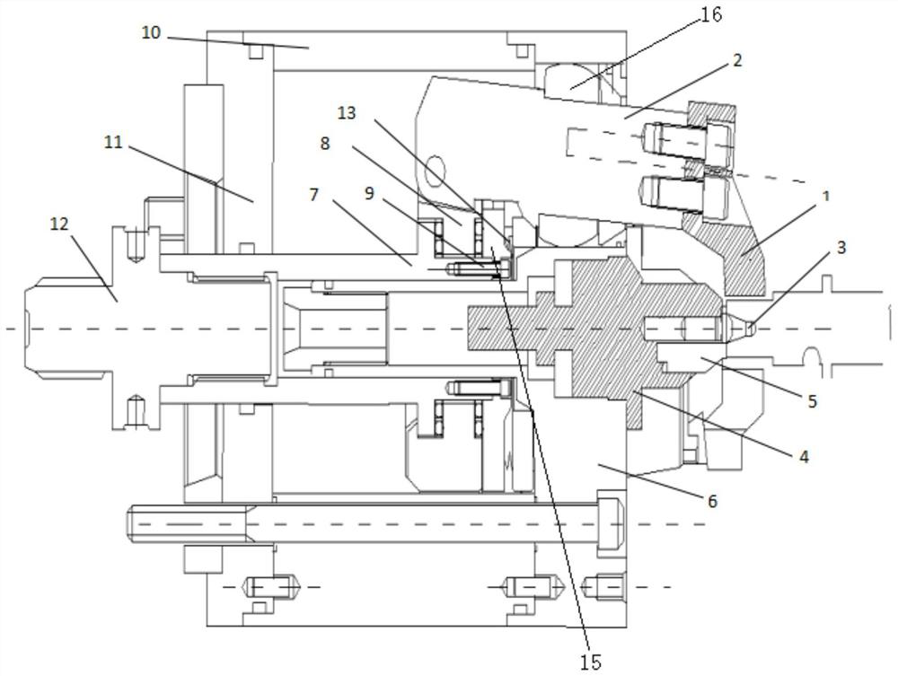
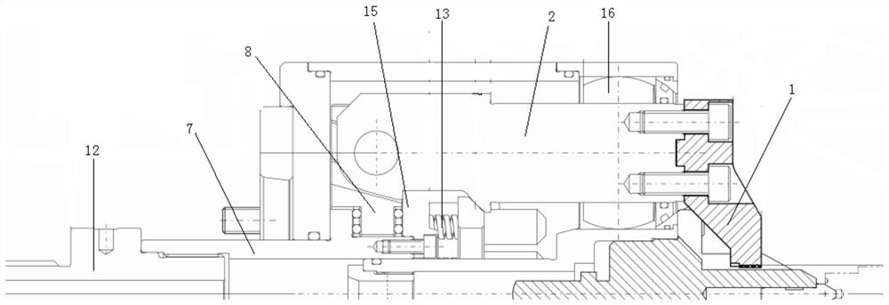
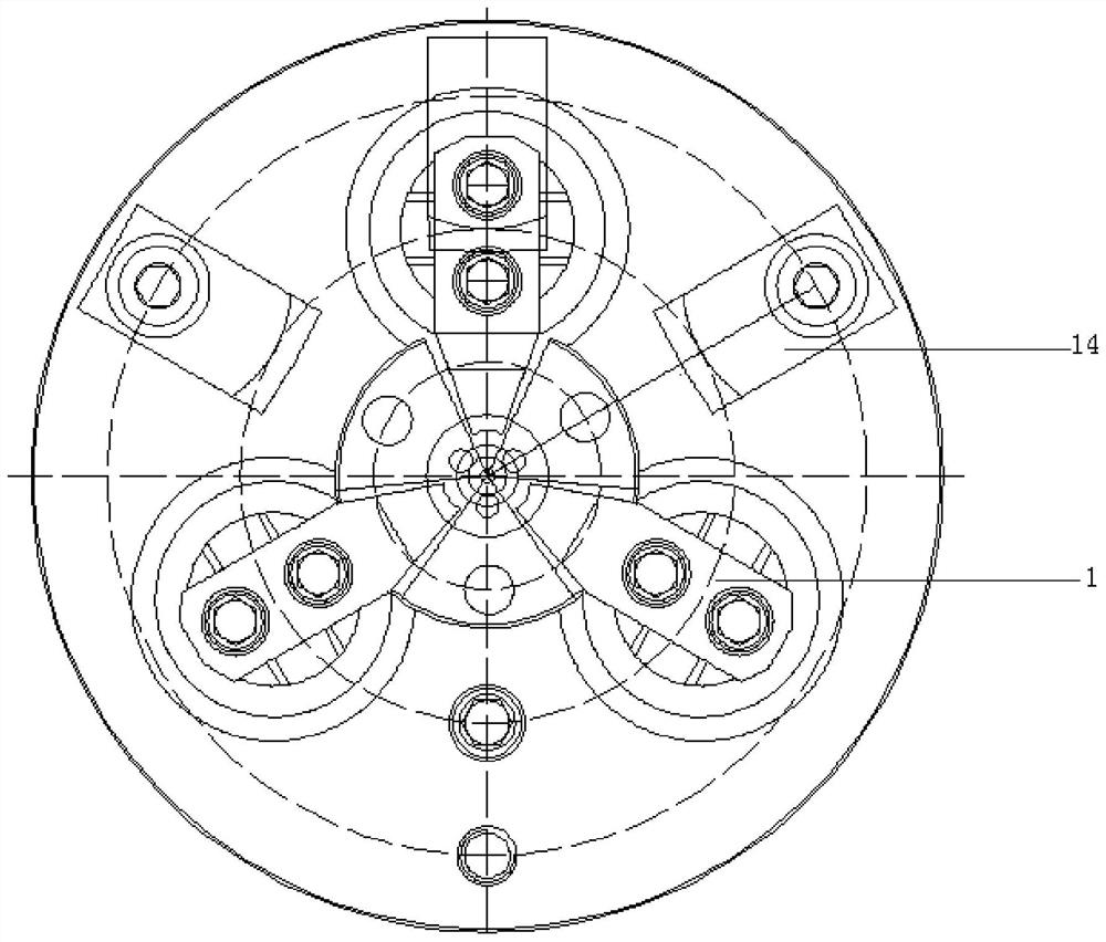
[0025] refer to Figure 1-3 , a kind of fixture for automobile engine balance shaft production, used for clamping and fixing during the processing and production of automobile engine balance shaft, comprising a clamp body 10, which is installed on a machine tool through a transition plate 11, and one end of the clamp body 10 is fixedly installed with a chuck 6, and the chuck The end drive 4 is fixedly installed on the disc 6, and the top 3 for centering the center hole of the balance shaft 17 is fixedly installed on the end drive 4. The top 3 is fixed by a tappet 5, and a plurality of pairs of balance shafts 17 are arranged on the outside of the chuck 6. The periphery carries out fixed retractable jaw 1.

[0026] Three grooves are evenly opened along the circumference on the end face drive 4, and three sliders 2 are uniformly arranged at the front end of the chuck in the chuck 6, and the telescopic jaws 1 are fixedly installed on the sliders 2, so that the three telescopic jaw...


PUM


Abstract

The invention relates to a production fixture of an automobile engine balance shaft. The production fixture is used for clamping and fixing the automobile engine balance shaft during processing and production. The production fixture comprises a fixture body; a chuck is fixedly installed at one end of the fixture body; an end face driver is fixedly installed on the chuck and fixedly provided with acentre for centering a center hole of the balance shaft; and a plurality of extensible clamping claws for fixing the periphery of the balance shaft are arranged on the outer side of the chuck. Compared with the prior art, the centre of the end face driver can be jacked into the center hole of the balance shaft to maintain centering reference consistency, high torque needed for rough turning operation can be transmitted through combination of clamping force provided by the three clamping claws and holding force provided by the end face driver, and the end face driver can complete machining ofall outer circles once being clamped, so that the balance shaft production efficiency is improved, and coaxiality and production precision are ensured.

Description

technical field [0001] The invention relates to the field of mechanical manufacturing, in particular to a production jig for an automobile engine balance shaft. Background technique [0002] The balance shaft of an automobile engine is generally arranged inside the engine and driven by a chain or a gear. When the engine is working, the sudden change in rotation speed produces vibration. An eccentric shaft can be installed to rotate together to offset this vibration. This shaft is the balance shaft. However, because the balance shaft is eccentric, traditional chucks are not easy to clamp during rough turning and hard turning, and secondary clamping is required during production, which reduces production efficiency and is difficult to guarantee coaxiality. Contents of the invention [0003] The object of the present invention is to provide a production jig for an automobile engine balance shaft in order to solve the above problems. [0004] The object of the present invent...

Claims


Application Information

Patent Timeline
Patent Type & Authority Patents(China)
IPC IPC(8): B23Q3/12
CPCB23Q3/12
Inventor 王锁宋新萍苏宁
Owner SHANGHAI UNIV OF ENG SCI
Learn More