Building material recycling and smashing device

A crushing device and technology for building materials, applied in the field of construction, can solve problems such as unfavorable later utilization, material jamming, and increased reuse costs, and achieve the effects of facilitating recycling, reducing operating failures, and improving operating efficiency

Inactive Publication Date: 2019-01-04
HENAN HUANQIU AVIATION EQUIP TECH CO LTD
View PDF13 Cites 2 Cited by
  • Summary
  • Abstract
  • Description
  • Claims
  • Application Information

AI Technical Summary

Problems solved by technology

The construction waste generated in construction projects is often large in size and difficult to crush thoroughly at one time. Part of the crushed construction waste is still large in size, which is not conducive to later utilization; ordinary construction waste treatment has only completed one process, and the crushed construction waste It cannot be used quickly and directly, and the storage and transportation of construction waste will increase the cost of reuse, which is not in line with the concept of environmental protection
[0003] Chinese patent (application publication number: CN107234724A) discloses a device for crushing and reusing construction waste. The invention uses the rotation of the lifting screw to drive the pressure plate and the filter screen in the scrap box to move closer to the middle, thereby squeezing and crushing the construction waste; However, there are also obvious defects in its operation. When the screw drive is used to drive the extrusion, it cannot effectively cause an instant impact force, so there will be a phenomenon of material jamming in actual operation.

Method used


Image

  • Building material recycling and smashing device
  • Building material recycling and smashing device
  • Building material recycling and smashing device

Examples


Embodiment 1

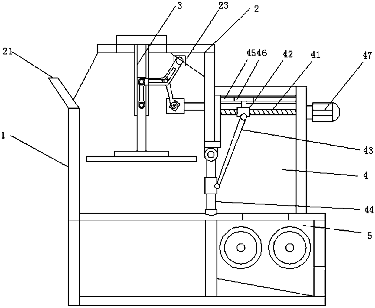
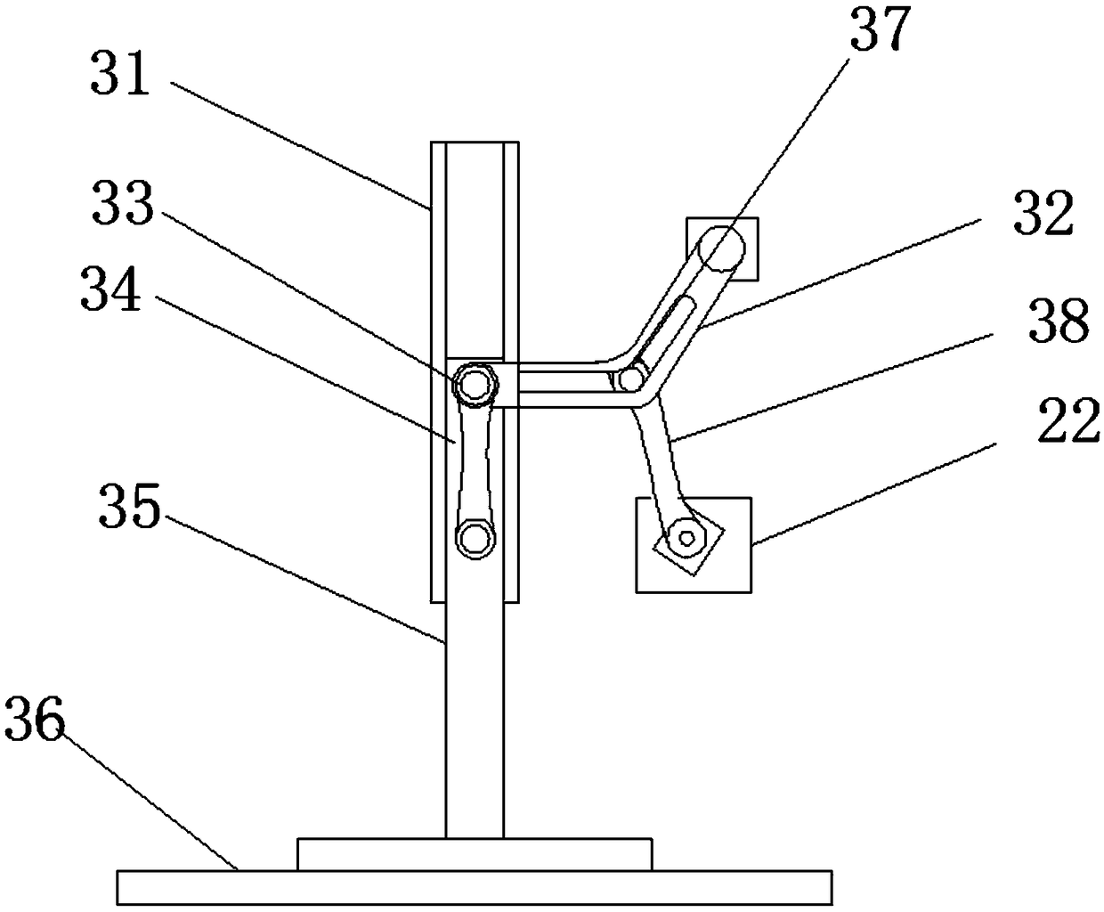
[0023] see figure 1 with figure 2 , a kind of building material recycling and crushing device, comprising a frame 1, the frame 1 is provided with an extrusion chamber 2, and a transmission frame 3 is installed in the extrusion chamber 2, and the transmission frame 3 includes a limit guide rail 31 and transmission guide rail 32, the limit guide rail 31 is installed on the top plate of the extrusion chamber 2, the fixed plate 23 is installed at the oblique position of the extrusion chamber 2, and the transmission guide rail 32 is installed on the erection plate through the movable shaft 23, a transmission block 33 is installed in the limit guide rail 31, a straight rod 35 is installed at the bottom end of the transmission block 33, an extrusion plate 36 is installed at the bottom end of the straight rod 35, and the extrusion chamber 2 A transmission plate 22 is installed on the side wall of the transmission plate 22, a first transmission rod 38 is installed on the top of the f...

Embodiment 2

[0026] As a further optimization of Embodiment 1, on the basis of it, a material delivery chamber 4 is also provided. The material delivery chamber 4 is located on the rear side of the extrusion chamber 2. It is connected with a feeding plate 44, and the feeding plate 44 is installed on the partition between the feeding chamber 4 and the extrusion chamber 2 through a movable shaft, and the top of the feeding chamber 4 is horizontally installed with a threaded rod 41 , the threaded rod 41 is installed with a drive sleeve 42 , and the connecting seat is installed on the surface of the feeding plate 44 , and the drive sleeve 42 and the connecting seat are connected through a tie rod 43 . A feeding motor 47 is installed on the rear side wall of the feeding chamber 4, and the threaded rod 41 is connected with the motor shaft of the feeding motor 47 through a coupling.

[0027] During operation, the feeding motor 47 drives the threaded rod 41 to rotate, drives the transmission sleev...

Embodiment 3

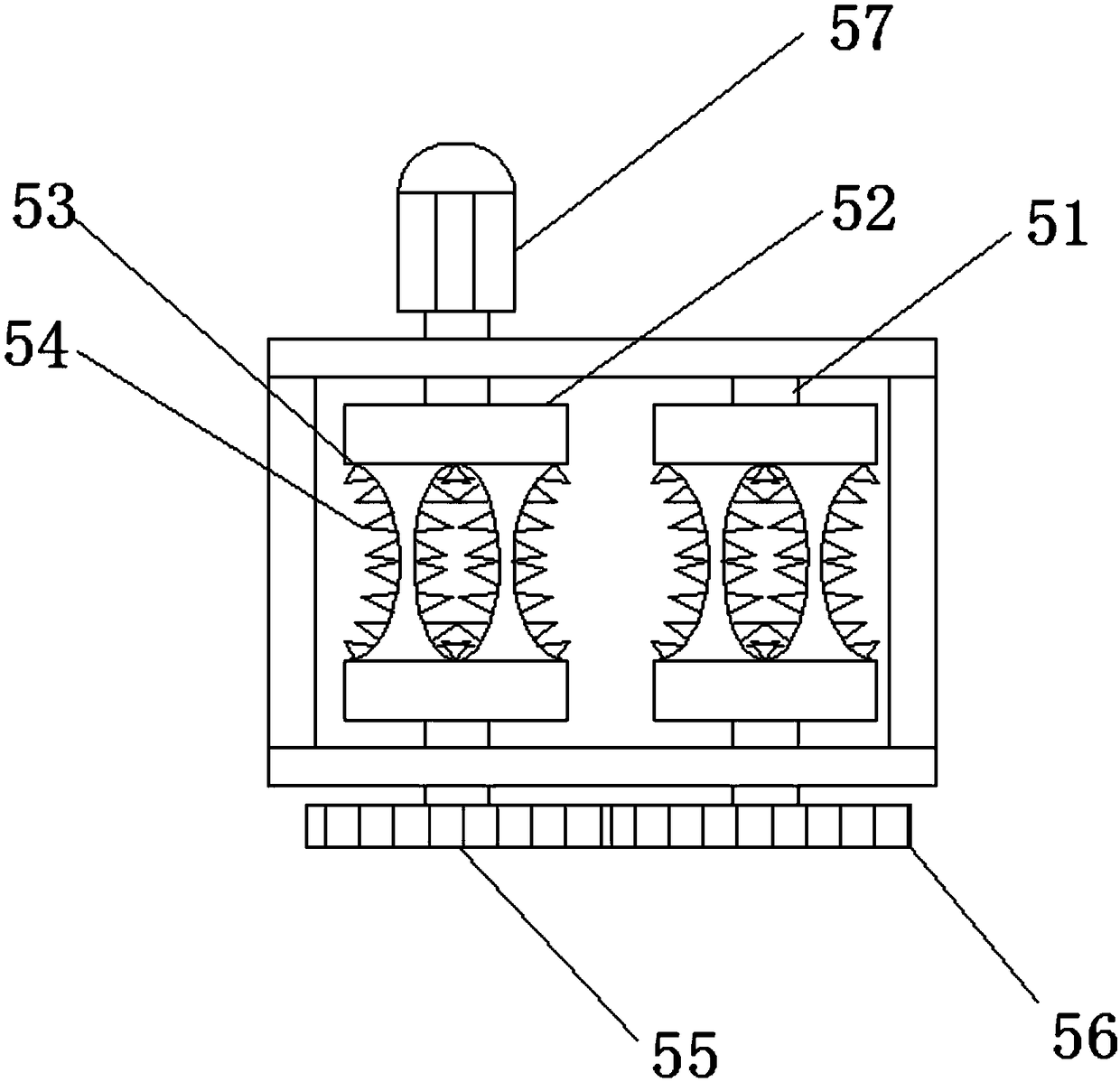
[0030] As a further optimization of the second embodiment, on the basis of it, the bottom end of the feeding chamber 4 is provided with a crushing chamber 5, and two roller shafts 51 are horizontally installed in the crushing chamber 5, and the roller shafts 51 A crushing roller 52 is installed on the top, and several grooves 53 are installed on the crushing roller 52, and crushing teeth 54 are arranged in the grooves 53, and the crushing rollers 52 on the left and right sides are arranged as left and right mirror images. A transmission gear 55 and a driven gear 56 are respectively installed on the front end of the roller shaft 51 , and the transmission gear 55 and the driven gear 56 are gear meshed. A transmission motor 57 is installed on the rear wall of the crushing chamber 5, and the motor shaft of the transmission motor 57 is connected with one of the roller shafts 51 through a coupling.

[0031] During operation, the material falls into the groove 53, and the crushing ro...


PUM


Abstract

The invention discloses a building material recycling and smashing device. The building material recycling and smashing device comprises a machine frame; the machine frame is provided with an extruding cavity, a transporting cavity and a smashing cavity; a transmission machine frame is mounted in the extruding cavity and comprises a limiting guide rail and a transmission guide rail; the limiting guide rail is mounted on a top plate of the extruding cavity; a fixed plate is mounted at the position of an oblique angle of the extruding cavity; the transmission guide rail is mounted on an erectionplate through a movable shaft; a transmission block is mounted in the limiting guide rail; a straight rod is mounted at the bottom end of the transmission block; an extruding plate is mounted at thebottom end of the straight rod; a transmission plate is mounted on a side wall of the extruding cavity; a first transmission rod is mounted on the transmission plate; and a clamping bolt is mounted atthe top end of the first transmission rod and in the transmission guide rail. According to the invention, the extruding plate is transmitted by a multi-stage connecting rod to extrude and smash material, and the effect of impacting the material powerfully can be achieved, so that the smashing efficiency of material can be ensured, and the situation of material jamming can be prevented.

Description

technical field [0001] The invention relates to the construction field, in particular to a building material recycling and crushing device. Background technique [0002] With the improvement of urbanization and the continuous transformation of old urban areas, old buildings are demolished almost every day, and most of the construction waste is transported to the suburbs or villages without any treatment, and is piled up or landfilled in the open air. It not only consumes a large amount of land and construction costs such as land acquisition, but also causes a huge waste of resources. If these building demolition objects can be reused, the high cost of handling will be avoided, the cost will be saved, and it can be remade into concrete for on-site reuse. The construction waste generated in construction projects is often large in size and difficult to crush thoroughly at one time. Part of the crushed construction waste is still large in size, which is not conducive to later u...

Claims


Application Information

Patent Timeline
Patent Type & Authority Applications(China)
IPC IPC(8): B02C1/00B02C4/02B02C23/00
CPCB02C1/00B02C4/02B02C23/00
Inventor 王飞
Owner HENAN HUANQIU AVIATION EQUIP TECH CO LTD
Why Eureka
Try Eureka