Motor

A stator and housing technology, applied in the direction of electrical components, electromechanical devices, electric components, etc., can solve the problems of unstable motor operation, reduced motor service life, deformation of motor structural parts, etc., to improve heat transfer effect and excellent motor performance , fast warm-up effect

Active Publication Date: 2019-01-01
浙江江宇电机有限公司
View PDF5 Cites 2 Cited by
  • Summary
  • Abstract
  • Description
  • Claims
  • Application Information

AI Technical Summary

Problems solved by technology

[0002] At present, in recent years, with the continuous development of the motor industry, motor manufacturers continue to pursue small size and high power density. More and more materials with high electromagnetic load and thermal load are used in motor design, and the loss generated during motor operation increases. The overall temperature rise of the motor is too high or the local temperature rise is too high, which will not only reduce the service life of the motor, affect the efficiency, torque and other economic and technical indicators of the motor, but also cause serious deformation of the structural parts of the motor, endangering the safety of the motor operation
In particular, the inner side of the stator, that is, the heat released by the rotor is accumulated in a large amount inside the housing, and it is difficult to transfer it out
In addition, during the working process of the existing motor, strong vibration will be generated due to the excessive rotation of the rotor, which will lead to unstable operation of the motor and affect the stable operation of the motor

Method used


Image

  • Motor
  • Motor
  • Motor

Examples


Embodiment Construction

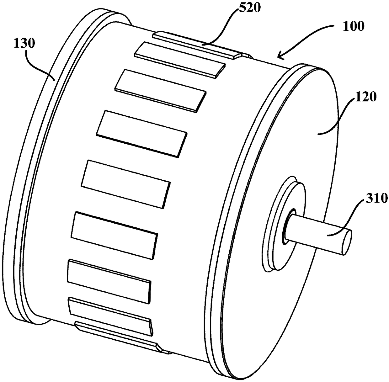
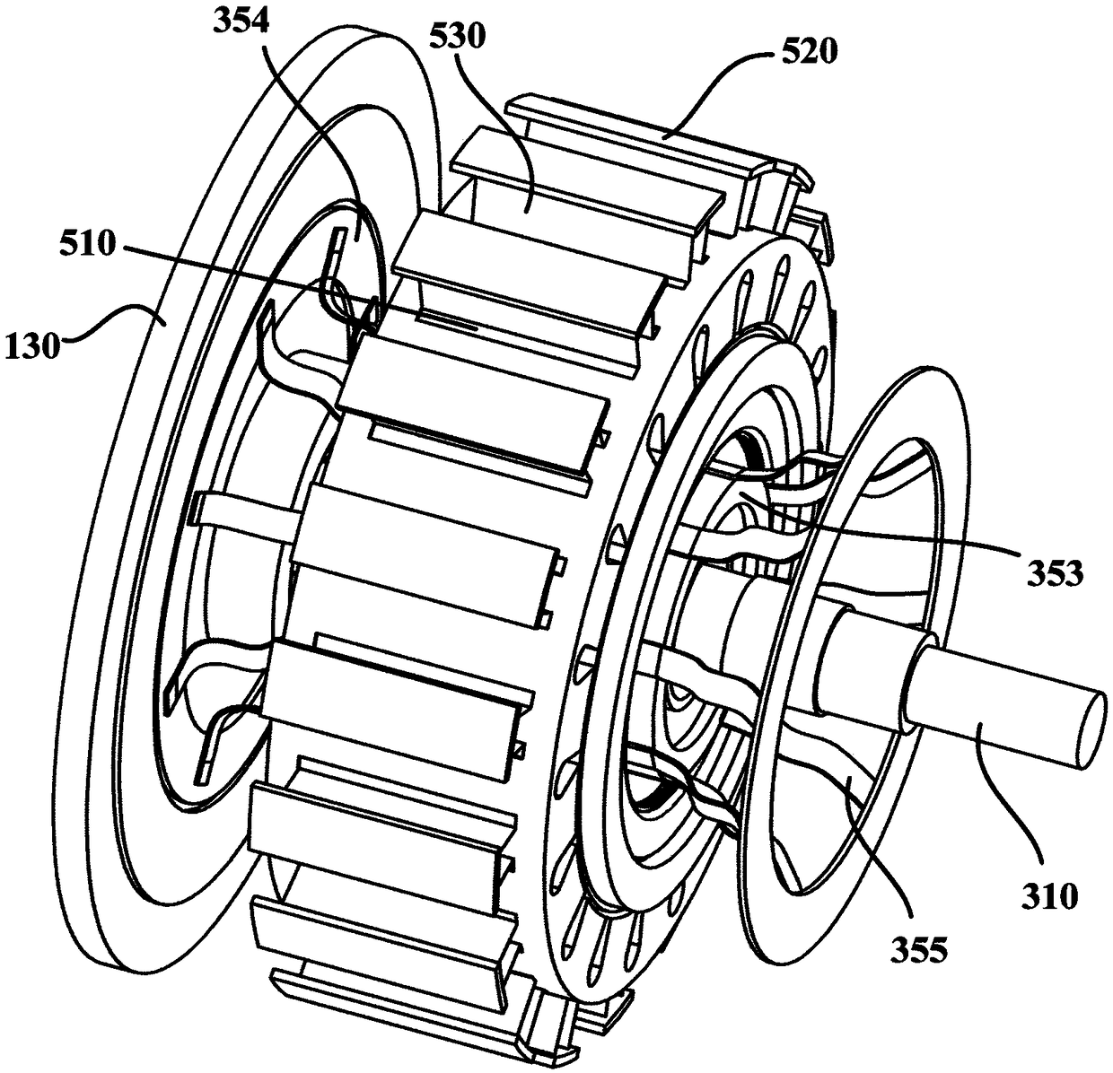
[0045] figure 1 is a schematic structural diagram of a motor according to an embodiment of the present invention. Such as figure 1 shown, and refer to figure 2 and image 3 , the embodiment of the present invention provides a motor. Generally, the motor may include a housing 100 , a stator 200 and a rotor 300 . The housing 100 generally has a main housing 110 and end covers disposed on two ends of the main housing 110 , such as a housing front cover 120 and a housing rear end cover 130 . The stator 200 is disposed in the housing 100 . The rotor 300 is disposed radially inside the stator 200 . The iron core of the stator 200 has stator slots 210 for winding windings 240 .

[0046]In particular, the stator core also has a plurality of heat transfer through holes. Each heat transfer through hole includes a first strip-shaped hole 220 opening toward the radially outer side of the stator, and a plurality of rectangular oil holes 230 opening toward the radially inner side o...


PUM


Abstract

The invention provides a motor. The motor includes a shell, a stator, and a rotor; a plurality of heat transfer through holes are formed in a stator core; each heat transfer through hole includes a first strip-shaped hole of which the opening faces the radial outer side of the stator, and a plurality of rectangular oil holes of which the openings face the radial inner side of the stator, wherein the rectangular oil holes are distributed along the length direction of the first strip-shaped hole at intervals; each first strip-shaped hole extends along the axial direction of the stator; each rectangular oil hole is communicated with the corresponding first strip-strip hole, so that each heat transfer through hole can be communicated with the inner side and outer side of the stator core; a plurality of second strip-shaped holes are formed in the shell; each second strip-shaped hole is corresponding to one first strip-shaped hole; the motor further comprises a plurality of heat conducting devices; and each heat conducting device comprises heat conducting sheets; one side of each heat conducting sheet is inserted into the bottom of the corresponding first strip-shaped hole, and the otherside of the heat conducting sheet is inserted at least into the bottom of the corresponding second strip-shaped hole, and therefore, the heat of the inner side of the stator core can be at least transferred to the shell. The motor has the advantages of high heat dissipation efficiency and excellent motor performance.

Description

technical field [0001] The invention relates to the field of motors, in particular to a motor with excellent heat dissipation. Background technique [0002] At present, in recent years, with the continuous development of the motor industry, motor manufacturers continue to pursue small size and high power density. More and more materials with high electromagnetic load and thermal load are used in motor design, and the loss generated during motor operation increases. If the overall temperature rise of the motor is too high or the local temperature rise is too high, it will not only reduce the service life of the motor, affect the efficiency, torque and other economic and technical indicators of the motor, but also cause serious deformation of the structural components of the motor, endangering the safety of the motor. In particular, the inner side of the stator, that is, the heat released by the rotor is accumulated in a large amount inside the housing, and it is difficult to ...

Claims


Application Information

Patent Timeline
Patent Type & Authority Applications(China)
IPC IPC(8): H02K9/22H02K1/20H02K5/20H02K9/197H02K5/04H02K5/24H02K5/167
Inventor 尹东升李晓宇尹洁
Owner 浙江江宇电机有限公司
Why Eureka
Try Eureka