
Multi-terminal flexible DC grid DC line quick protection method and system based on single-terminal voltage

A DC power grid, multi-terminal flexible technology, applied in emergency protection circuit devices, information technology support systems, electrical components and other directions, can solve the problems of line protection misoperation, difficult to meet the requirements of quick action, no reliable and mature methods, etc. Achieving the effect of strong quickness and high sensitivity

Active Publication Date: 2019-01-01
SHANDONG UNIV +2
View PDF11 Cites 58 Cited by
  • Summary
  • Abstract
  • Description
  • Claims
  • Application Information

AI Technical Summary

Problems solved by technology

However, this method needs to accurately locate the fault line in a very short period of time. At present, there is no reliable and mature method. Therefore, a new line protection principle that can meet the selectivity and rapidity of the flexible straight grid is urgently needed.
[0004] The existing technology proposes a protection method based on double-ended quantities. Although this method has good selectivity, it cannot be used as the main protection for flexible straight grid lines because of the communication delay and it is difficult to meet the requirements of quick action.
[0005] The existing technology proposes a protection method based on low voltage, overcurrent, current differential, and voltage differential. This method can meet the requirements of quick action, but due to the influence of transition resistance and other factors, the sensitivity of the above protection principle is difficult to guarantee. The removal of the adjacent fault line may also cause the protection of this line to malfunction

Method used


Image

  • Multi-terminal flexible DC grid DC line quick protection method and system based on single-terminal voltage
  • Multi-terminal flexible DC grid DC line quick protection method and system based on single-terminal voltage
  • Multi-terminal flexible DC grid DC line quick protection method and system based on single-terminal voltage

Examples


Embodiment Construction

[0068] It should be pointed out that the following detailed description is exemplary and intended to provide further explanation to the present application. Unless defined otherwise, all technical and scientific terms used herein have the same meaning as commonly understood by one of ordinary skill in the art to which this application belongs.

[0069] It should be noted that the terminology used here is only for describing specific implementations, and is not intended to limit the exemplary implementations according to the present application. As used herein, unless the context clearly dictates otherwise, the singular is intended to include the plural, and it should also be understood that when the terms "comprising" and / or "comprising" are used in this specification, they mean There are features, steps, operations, means, components and / or combinations thereof.

[0070] The invention discloses a fast protection method for DC lines of a multi-terminal flexible DC power grid ...


PUM


Abstract

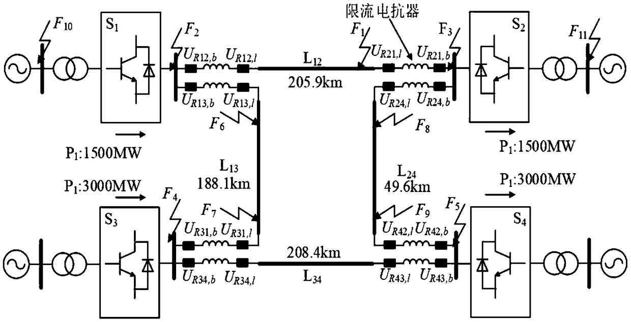
The invention discloses a multi-terminal flexible DC grid DC line quick protection method and system based on single-terminal voltage. The method comprises the following steps: collecting the voltagesignals on the two sides of DC positive and negative line current limiting reactors in real time; forming a low voltage starting criterion; performing wavelet transform on the calculated line mode voltage on the current limiting reactors and calculating the wavelet transform modulus maximum; performing the data validity test and recording the size and the symbol of the first wavelet transform modulus maximum meeting the data validity condition; establishing the fault identification criterion to identify the fault based on the symbol and amplitude difference of the single-terminal voltage traveling wave wavelet transform modulus maximum; and constructing the fault pole identification criterion to identify the fault pole based on the size difference of the voltage traveling wave transient energy. According to the line protection method, the fault direction can be reliably and quickly identified under various initial fault conditions, and the transition resistance, the fault location andthe fault of the AC system and other factors have little influence on the protection criterion so as to have high reliability and sensitivity.

Description

technical field [0001] The invention relates to the technical field of DC power grid line fault protection, in particular to a method and system for fast protection of DC lines in a multi-terminal flexible DC power grid based on single-ended voltage. Background technique [0002] Compared with AC power grids and conventional high-voltage direct current transmission systems, multi-terminal flexible DC power grids based on voltage source converters have great advantages in large-scale new energy grid integration, regional grid interconnection, and central load power supply. However, due to the small damping of the flexible DC system, the fault develops rapidly after the fault on the DC side, and the fault current will rise to a maximum value within a few milliseconds, endangering the safety of the entire DC grid. Therefore, in order to clear the fault before the converter station is blocked and ensure the safe and reliable operation of the sound line after the fault, the fault...

Claims


Application Information

Patent Timeline
IPC IPC(8): H02H7/26G01R31/08
CPCG01R31/085H02H7/265H02H7/268Y04S10/52
Inventor 邹贵彬张烁魏秀燕黄强谢仲润孙辰军
Owner SHANDONG UNIV
Learn More