Front-lifting type double-contact connector

A connector and double-contact technology, which is applied in the direction of connection, parts of connection devices, protective grounding/shielding devices of connection parts, etc., can solve inconvenient insertion, high installation requirements, and inability to insert wrong FPC/FFC cables, etc. problem, to achieve the effect of easy opening of the flip cover, not easy to fall off, and simple structure

Pending Publication Date: 2019-01-01
CVILUX TECH SUZHOU
View PDF15 Cites 0 Cited by
  • Summary
  • Abstract
  • Description
  • Claims
  • Application Information

AI Technical Summary

Problems solved by technology

The FPC / FFC connector at the insertion end of the cover plate can only be used with the contact surface facing down, which has high requirements for installation, and the FPC / FFC cable cannot be inserted in the wrong direction
The connector whose cover plate is far away from the insertion end has a small cable slot, and the FPC / FFC cable needs to be aligned with the cable slot to be inserted accurately, which is inconvenient to insert.

Method used


Image

  • Front-lifting type double-contact connector
  • Front-lifting type double-contact connector
  • Front-lifting type double-contact connector

Examples


Embodiment 1

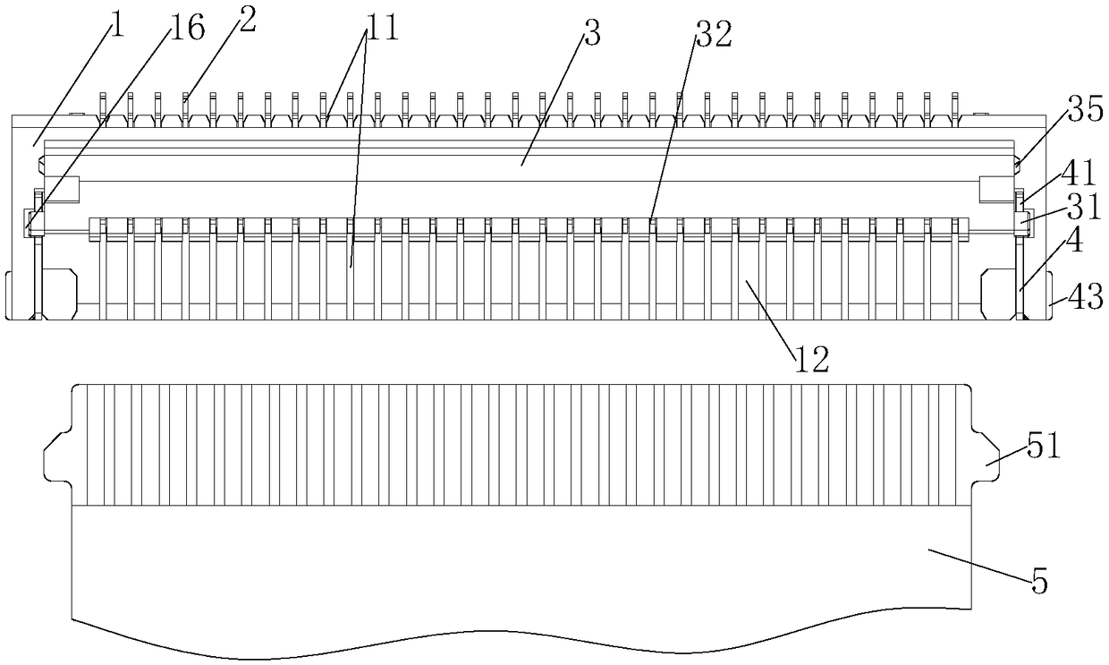
[0039] Such as Figure 1 to Figure 7 As shown, the front flip-type dual-contact connector includes an insulating base 1, a flip cover 3, a conductive terminal 2, and a ground terminal 4. The front end of the insulating base 1 is provided with a cable slot 13 and a grounding slot 14, and the grounding plug The slots 14 are located at both ends of the insulating base 1, and the grounding terminals 4 are inserted into the grounding slots 14. The rear end of the insulating base 1 is arrayed with a plurality of terminal slots 11, and the terminal slots 11 communicate with the cable slot 13 and are conductive. The terminal 2 is inserted in the terminal slot 11, the conductive contact of the conductive terminal 2 is located in the cable slot 13, the top of the insulating base 1 is provided with a cover plate groove 12, and the flip cover 3 is rotatably installed in the cover plate groove 12.

[0040] Such as Figure 1 to Figure 4 As shown, the cover slot 12 passes through the front end ...

Embodiment 2

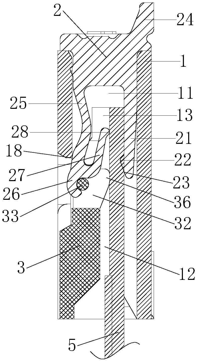
[0055] On the basis of the first embodiment, the upper elastic arm 25 is also provided with a compression elastic arm 27, and an elastic groove 271 is provided between the compression elastic arm 27 and the upper elastic arm 25, and the elastic arm 27 and the upper elastic arm are compressed. 25 is U-shaped, and the upper conductive contact 28 is located at the end of the elastic pressing arm 27.

[0056] Compressing the elastic arm 27 can increase a larger deformation space, and can be applied to FFC cables 5 of different thicknesses.


PUM


Abstract

The invention relates to a front-lifting type double-contact connector. A conductive terminal array is disposed on an insulating seat, and a lifting cover is rotatably mounted in a cover slot of the insulating seat. Grounding terminals are fixed at both ends of the insulating seat, and one end of the conductive terminal is provided with a soldering leg, and the other end is provided with an upperelastic arm and a lower elastic arm, wherein the upper elastic arm and the lower elastic arm are respectively provided with an upper conductive contact and a lower conductive contact. A limiting hookof the end of the upper elastic arm is movably inserted in a terminal groove of the lifting cover and is pressed above a limiting shaft. The limiting hook is used for limiting the rotating shaft of the lifting cover in a rotating slot. A pressing boss on the rotating shaft is used for pressing a FFC cable to the lower conductive terminal. The intersection of the cover slot with a cable slot is taken as the fulcrum. The limiting shaft and the fulcrum are used to press the upper conductive contact on the upper elastic arm toward the FFC cable. The connector has a simple structure, and the lifting cable is easy to open. The FFC cable can be inserted easily and quickly, and the FFC cable can be pressed from the front and back sides of the FFC cable. The contact is good, and the FFC cable is not easy to fall off.

Description

Technical field [0001] The invention relates to a connector, in particular to a front lift type double contact connector. Background technique [0002] The connection between the FFC / FPC cable and the circuit board needs to be completed through the FFC connector, that is, the FFC cable and the FFC connector need to be connected and assembled. The FFC connector includes a base and a cover. The base is equipped with contact terminals and a cover. Stuck on the base. When assembling, first remove the cover from the base of the FFC connector, then insert the FFC cable into the contact terminal in the FFC connector, and then press the FFC cable on the base through the cover. Since most of the FFC connectors adopt a horizontal structure, it brings inconvenience to the plug operation, and the structure design is not reasonable enough, the structure is complicated, and the use is inconvenient. FFC cable insertion requires a certain amount of force and skill, and it must be kept perpendi...

Claims


Application Information

Patent Timeline
Patent Type & Authority Applications(China)
IPC IPC(8): H01R13/40H01R13/502H01R13/627H01R13/629H01R13/652
CPCH01R13/40H01R13/502H01R13/627H01R13/629H01R13/652
Inventor 邱显钰
Owner CVILUX TECH SUZHOU
Why Eureka
Try Eureka