
Narrow edge electro-dimming device

An electro-dimming and device technology, which is applied in the field of automotive mirrors, can solve the problems that affect the uniformity of device dimming, large edge width, and voltage loss, so as to improve the uniformity of dimming, reduce the width of the edge, and improve long-term stability The effect of sex and appearance

Pending Publication Date: 2019-01-01
CHANGZHOU YAPU NEW MATERIALS CO LTD
View PDF6 Cites 1 Cited by
  • Summary
  • Abstract
  • Description
  • Claims
  • Application Information

AI Technical Summary

Problems solved by technology

[0003] The purpose of the present invention is to provide a narrow-side electroluminescent device to solve the problem that the edge width of the electroluminescent device in the prior art is relatively large, which causes voltage loss and causes uneven electric field distribution between the two thin-film electrode plates, which ultimately affects the device. The problem of dimming uniformity

Method used


Image

  • Narrow edge electro-dimming device
  • Narrow edge electro-dimming device
  • Narrow edge electro-dimming device

Examples


Embodiment Construction

[0019] The following will clearly and completely describe the technical solutions in the embodiments of the present invention with reference to the drawings in the embodiments of the present invention. Apparently, the described embodiments are only some of the embodiments of the present invention, but not all of them. Based on the embodiments of the present invention, all other embodiments obtained by persons of ordinary skill in the art without making creative efforts belong to the protection scope of the present invention.

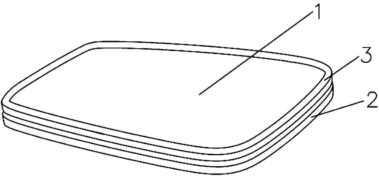
[0020] see Figure 1 to Figure 3 , the present invention provides a technical solution: a

[0021] The narrow-side electroluminescent device includes a conductive transparent glass 1 and a reflective conductive glass 2 with the same shape and size, the conductive transparent glass 1 and the reflective conductive glass 2 are attached to each other, and the conductive transparent glass 1 is back-reflected One side surface of the conductive glass 2 is sur...


PUM


Abstract

The invention relates to the technical field of automobile sight glass, and especially relates to a narrow edge electro-dimming device. The device includes conductive transparent glass and reflectiveconductive glass with same shapes and sizes; the conductive transparent glass and the reflective conductive glass are in mutual fitting arrangement; the surface of the side, back toward the reflectiveconductive glass, of the conductive transparent glass is circumferentially provided with a reflective masking ring along the edge; a sealant is arranged between the conductive transparent glass and the reflective conductive glass, and is circumferentially arranged on the edge of the reflective conductive glass; one side of the conductive transparent glass is provided with a first electrical insulation chamfer; and the side, away from the first electrical insulation chamfer, of the reflective conductive glass is provided with a second electrical insulation chamfer. Thus, the dimming uniformityof the device can be effectively improved, the width of non-dimming regions on the edge of the device can be effectively decreased, and the beauty of the appearance of the device can be enhanced.

Description

technical field [0001] The invention relates to the technical field of automobile mirrors, and specifically relates to a narrow-edge electroluminescence adjustment device. Background technique [0002] An electroluminescent device refers to a device in which a specific functional material sealed between two electrodes has optical properties changed under the action of an external power source. The electrode materials of the device can be electrochemically stable metals, carbon, and conductive inorganic oxides, which are usually deposited on glass substrates as thin film electrodes. Due to the high surface resistance value of the thin film electrode, the voltage loss caused by it will lead to uneven distribution of the electric field between the two thin film electrode plates, and ultimately affect the dimming uniformity of the device. In order to improve this problem, one of the existing methods is to implement a certain dislocation of the two thin-film electrodes, and coat...

Claims


Application Information

Patent Timeline
Patent Type & Authority Applications(China)
IPC IPC(8): G02F1/155G02F1/153
CPCG02F1/153G02F1/155
Inventor 郑建明徐春叶
Owner CHANGZHOU YAPU NEW MATERIALS CO LTD
Learn More