Photocoupler testing device

A test device and optocoupler technology, which is applied in the field of optocoupler testing, can solve the problems of low efficiency and long time consumption, and achieve the effect of many test parameters, low cost and low equipment cost

Inactive Publication Date: 2019-01-01
WAHLAP TECH CO LTD
View PDF11 Cites 2 Cited by
  • Summary
  • Abstract
  • Description
  • Claims
  • Application Information

AI Technical Summary

Problems solved by technology

[0003] In order to overcome the time-consuming and low-efficiency shortcomings of building circuits one by one in the prior art, the present invention provides an optocoupler testing device with low cost, many detection parameters, and improved product quality and detection efficiency

Method used


Image

  • Photocoupler testing device
  • Photocoupler testing device
  • Photocoupler testing device

Examples


Embodiment Construction

[0026] The present invention will be further described below in conjunction with accompanying drawing and specific embodiment:

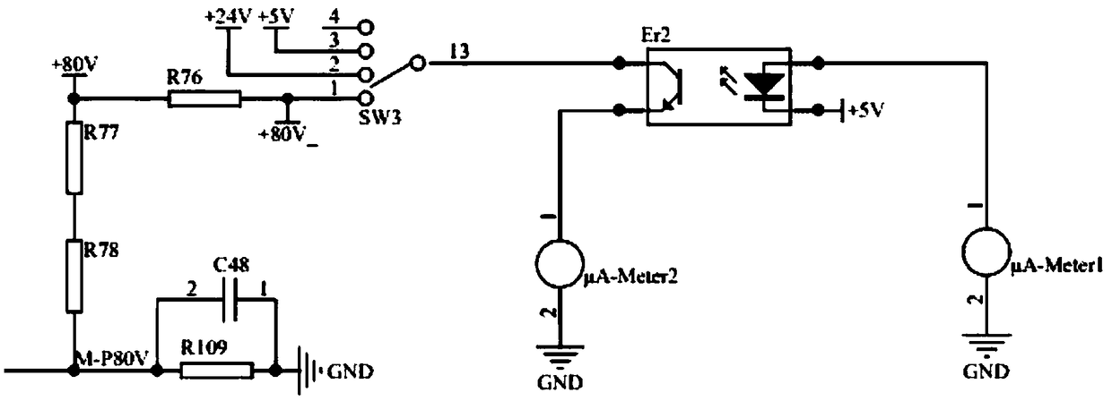
[0027] like figure 1 The shown embodiment is a kind of optocoupler testing device, comprises power supply module 1, MCU module 2, communication module 3, first test module 4, second test module 5 and the 3rd test module 6; Described power supply module comprises the 1st test module A DC / DC conversion module 11, a second DC / DC conversion module 12 and a third DC / DC conversion module 13; the first DC / DC conversion module is electrically connected to the second test module, and the second DC / DC conversion module is respectively connected to The first test module, the second test module and the third test module are electrically connected, and the third DC / DC conversion module is electrically connected to the MCU module; the MCU module is respectively connected to the communication module, the first test module, the second test module and the third test ...


PUM


Abstract

The invention discloses a photocoupler testing device, which comprises a power module, an MCU module, a communication module, a first testing module, a second testing module and a third testing module, wherein the power module is electrically connected with the MCU module, the communication module, the first testing module, the second testing module and the third testing module respectively; and the MCU module is electrically connected with the communication module, the first testing module, the second testing module and the third testing module respectively. The electrical appliance parameters of the photocoupler are measured respectively by the first testing module, the second testing module and the third testing module respectively, the device has a low price, the detected parameters are multiple, the product quality and the detection efficiency can be improved, the product fault rate is reduced, and the overall stability is improved.

Description

technical field [0001] The invention relates to the technical field of optocoupler testing, in particular to an optocoupler testing device with low cost, multiple detection parameters, and improved product quality and detection efficiency. Background technique [0002] Optocoupler, also known as photoelectric isolator, generally consists of three parts: light emission, light reception, and signal amplification. It uses light as a medium to transmit electrical signals. Optocoupler includes light emitter and light receiver. The light emitter and the light receiver are packaged in the same shell. When the input signal is powered, the light emitter emits light, and the light receiver generates photocurrent after receiving the light. The photocurrent flows out from the output end after further amplification, thus realizing the "electricity Light-to-electricity conversion. Due to the large number of electrical parameters of optocouplers, it takes a long time to build circuits one...

Claims


Application Information

Patent Timeline
Patent Type & Authority Applications(China)
IPC IPC(8): G01R31/00
CPCG01R31/00
Inventor 乐玉香陈超彭登富
Owner WAHLAP TECH CO LTD
Why Eureka
Try Eureka