
A system for transparent display and quantitative characterization of stress field in tunnel lining structure

A technology of transparent display and structural stress, applied in the testing, measuring devices, instruments, etc. of machine/structural components, which can solve the problems of long cycle, verification, influence of processing method, etc.

Active Publication Date: 2020-06-30
CHINA UNIV OF MINING & TECH (BEIJING)
View PDF14 Cites 0 Cited by
  • Summary
  • Abstract
  • Description
  • Claims
  • Application Information

AI Technical Summary

Problems solved by technology

In the numerical simulation method, the deviation between the geometric features and the real structure caused by the simplification of the numerical calculation model, the grid coverage mode, the contact and separation of the elements, the solution algorithm, the selection of material parameters, the determination of the constitutive relationship, the calculation scale and efficiency, etc. A series of problems have not been satisfactorily resolved, especially the calculation results are difficult to be verified by experiments or on-site construction parameters, which has caused some disputes or doubts
For laboratory measurement methods, the processing method of the model, material parameters, experimental conditions, accuracy of measuring instruments, load application methods, experimental equipment layout, and inherent size effects of the experimental model will have a greater impact on the experimental test results.
The on-site monitoring and measurement method has the disadvantages of large investment, long period, and measurement accuracy is greatly affected by the environment.

Method used


Image

  • A system for transparent display and quantitative characterization of stress field in tunnel lining structure
  • A system for transparent display and quantitative characterization of stress field in tunnel lining structure
  • A system for transparent display and quantitative characterization of stress field in tunnel lining structure

Examples


Embodiment Construction

[0035] The following will clearly and completely describe the technical solutions in the embodiments of the application with reference to the drawings in the embodiments of the application. Apparently, the described embodiments are only some of the embodiments of the application, not all of them. Based on the embodiments in this application, all other embodiments obtained by persons of ordinary skill in the art without making creative efforts belong to the scope of protection of this application.

[0036] Aiming at the deficiencies of various existing methods for characterizing the stress field distribution of lining structures, it is particularly important to develop an accurate, fast, cheap, and intuitive new method for quantitatively characterizing the distribution of stress fields in lining structures, which was rarely considered in the past. There are mainly two reasons for this situation.

[0037] On the one hand, before the emergence of 3D printing technology, it was di...


PUM


Abstract

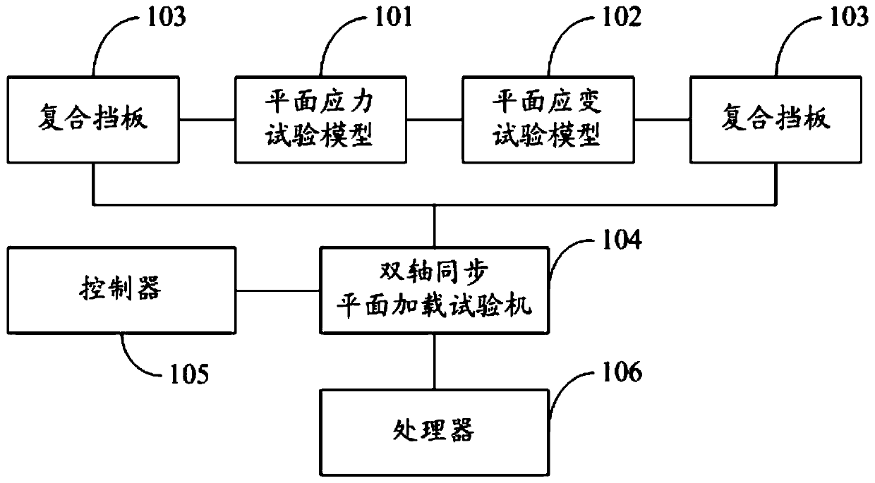
The invention discloses a transparent display and quantitative characterization system for a stress field of a tunnel lining structure. The system comprises a plane stress test model, a plane strain test model, two composite baffles, a two-axis synchronous plane loading test machine, a controller and a processor. The plane stress test model and the plane strain test model form a test model. The two composite baffles are used for fixing the test model; and the test model is clamped in the two-axis synchronous plane loading test machine. The controller controls the two-axis synchronous plane loading test machine to work and outputs a stress-strain curve; stripe pictures under all pressure gradients are obtained by combining a four-step phase shift method of white light and the six-step phaseshift method of monochromatic light; the processor obtains full-field stress difference distribution based on the stripe pictures; and with the stress separation means, full-field stress distributionof the test model under different load conditions is obtained. Therefore, the stress field distribution rule of the lining structure is characterized quantitatively, accurately, quickly, conveniently, and visually.

Description

technical field [0001] The present application relates to the technical field of static stress field measurement, in particular to a system for transparent display and quantitative characterization of the stress field of tunnel lining structures. Background technique [0002] With the continuous development of my country's economic level, subway or light rail has become one of the necessary means of transportation for people's daily travel. In the process of subway construction, determining the tunnel excavation scheme is a very important issue. Due to the fast construction speed and negligible effect on ground structures, the current shield machine excavation method occupies an absolutely dominant position in subway tunnel excavation technology, and lining structures are usually used for support in subway shield excavation tunnels surrounding rock to prevent its collapse. When designing the tunnel surrounding rock lining structure, only by knowing the deformation and fail...

Claims


Application Information

Patent Timeline
Patent Type & Authority Patents(China)
IPC IPC(8): G01M99/00
CPCG01M99/007
Inventor 鞠杨万昌兵刘赛王建强刘红彬刘鹏
Owner CHINA UNIV OF MINING & TECH (BEIJING)
Learn More