Steel bar truss floor slab structure
A steel truss and floor slab technology, applied in the field of steel truss floor slab structure, can solve the problems of weak concrete connection, insufficient support strength, and affecting service life, etc., to solve the problem of insufficient surface adhesion and relay force, ensure connection force, The effect of enhancing firmness
- Summary
- Abstract
- Description
- Claims
- Application Information
AI Technical Summary
Problems solved by technology
Method used
Image
Examples
Embodiment 1
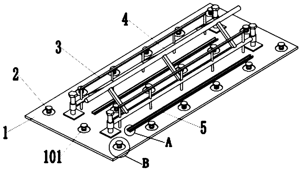
[0030] see Figure 1-6 , a reinforced truss floor structure, comprising a steel plate 1, a reinforced truss 4, and also includes connecting piles 2, auxiliary braces 3, the steel plate 1 is evenly provided with connecting piles 2, and the reinforced truss 4 includes a main beam 6, connecting Rod 7, connecting pillar 8, described main beam 6 comprises upper strut 601, side strut 602, the quantity of described side strut 602 is two, two side struts 602 are arranged in parallel, each side strut 602 The ends of each are provided with connecting struts 8, the upper struts 601 are arranged in the middle of the upper side of the two side struts 602, and the connecting rods 7 are arranged between the upper struts 601 and the side struts 602. The auxiliary bracket 3 is welded and fixed to the steel plate 1 and the side brace 602 respectively.
Embodiment 2
[0032] In this embodiment, a steel bar truss floor structure includes a steel plate 1, a steel bar truss 4, and connecting piles 2 and auxiliary braces 3. The steel plate 1 is evenly provided with connecting piles 2, and the steel bar truss 4 includes Main crossbeam 6, connecting rod 7, connecting pillar 8, described main crossbeam 6 comprises upper strut 601, side strut 602, the quantity of described side strut 602 is two, two side struts 602 are arranged in parallel, each The ends of the root side struts 602 are provided with connecting struts 8, and the upper struts 601 are arranged in the middle of the upper sides of the two side struts 602, and there is a connection between the upper struts 601 and the side struts 602. Rod 7, the auxiliary bracket 3 is welded and fixed to the steel plate 1 and the side brace 602 respectively.
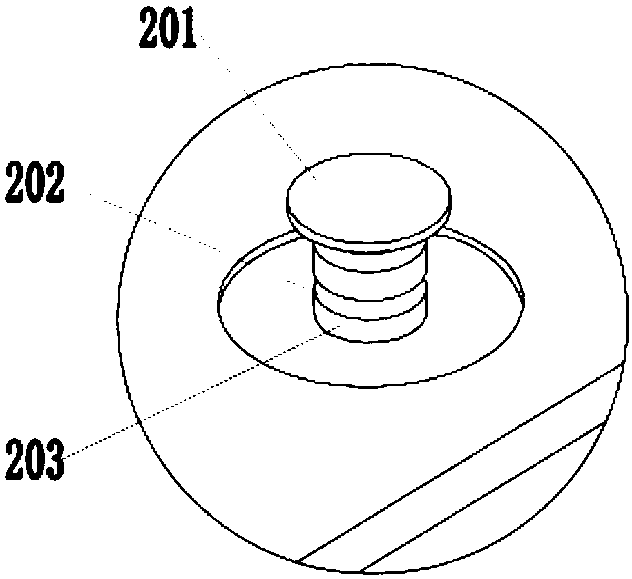
[0033] In this embodiment, the upper end surface of the steel plate 1 is provided with a groove 101, and the connecting pile 2 includes an anti-of...
Embodiment 3
[0035] In this embodiment, a steel bar truss floor structure includes a steel plate 1, a steel bar truss 4, and connecting piles 2 and auxiliary braces 3. The steel plate 1 is evenly provided with connecting piles 2, and the steel bar truss 4 includes Main crossbeam 6, connecting rod 7, connecting pillar 8, described main crossbeam 6 comprises upper strut 601, side strut 602, the quantity of described side strut 602 is two, two side struts 602 are arranged in parallel, each The ends of the root side struts 602 are provided with connecting struts 8, and the upper struts 601 are arranged in the middle of the upper sides of the two side struts 602, and there is a connection between the upper struts 601 and the side struts 602. Rod 7, the auxiliary bracket 3 is welded and fixed to the steel plate 1 and the side brace 602 respectively.
[0036] In this embodiment, the upper end of the steel plate 1 is provided with a perfusion groove 102, the perfusion groove 102 is a rectangular n...
PUM
 Abstract
Description
Claims
Application Information
 - R&D Engineer
- R&D Manager
- IP Professional
- Industry Leading Data Capabilities
- Powerful AI technology
- Patent DNA Extraction
Browse by: Latest US Patents, China's latest patents, Technical Efficacy Thesaurus, Application Domain, Technology Topic, Popular Technical Reports.
© 2024 PatSnap. All rights reserved.Legal|Privacy policy|Modern Slavery Act Transparency Statement|Sitemap|About US| Contact US: help@patsnap.com


