
A petroleum hydrocarbon catalytic cracking device

A catalytic cracking, petroleum hydrocarbon technology, applied in catalytic cracking, petroleum industry, cracking and other directions, can solve the problems of insufficient catalytic efficiency, troublesome replacement and maintenance, limited contact surface, etc., and achieve high catalytic cracking efficiency, easy operation, and reduced heating rate. Effect

Active Publication Date: 2020-11-24
六安维奥智能科技有限公司
View PDF4 Cites 0 Cited by
  • Summary
  • Abstract
  • Description
  • Claims
  • Application Information

AI Technical Summary

Problems solved by technology

[0003] The contact surface between the current catalyst and petroleum is limited, the catalytic efficiency is insufficient, and it is troublesome to replace and maintain; when cooling and collecting petroleum mixed gas, it needs to consume a lot of energy to ensure the temperature in each cooling equipment

Method used


Image

  • A petroleum hydrocarbon catalytic cracking device
  • A petroleum hydrocarbon catalytic cracking device
  • A petroleum hydrocarbon catalytic cracking device

Examples


Embodiment Construction

[0028] In order to make the technical means, creative features, goals and effects achieved by the present invention easy to understand, the present invention will be further described below in conjunction with specific embodiments.

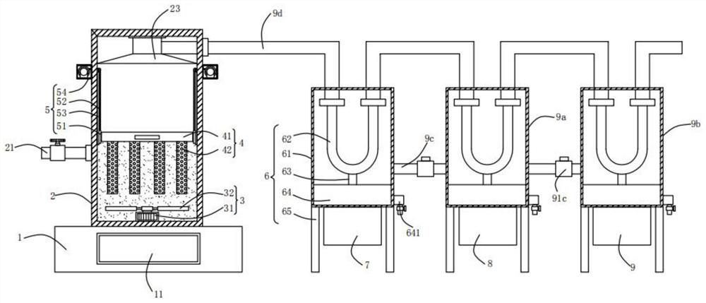
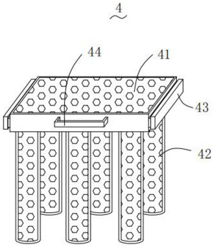
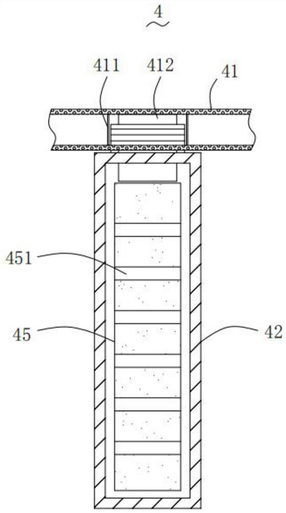
[0029] Such as Figure 1-Figure 6As shown, a petroleum hydrocarbon catalytic cracking device according to the present invention includes a base 1, a casing 2, a stirring mechanism 3, a storage mechanism 4, a traction mechanism 5, a first separation mechanism 6, a first cooling box 7, a second Cooling box 8, the third cooling box 9, the second separation mechanism 9a, the third separation mechanism 9b, cold air pipe 9c and air delivery pipe 9d; the top of the base 1 is provided with the box body 2; The stirring mechanism 3 is installed on the inner bottom, and the stirring mechanism 3 is used to stir the oil; the storage mechanism 4 is installed in the inside of the box 2, and the storage mechanism 4 is used to store the catalyst; The mechanism 4 ...


PUM


Abstract

The invention relates to the technical field of petroleum processing equipment, in particular to a catalytic cracking device for petroleum hydrocarbon. The catalytic cracking device comprises a base,a tank body, a stirring mechanism, a storing mechanism, a traction mechanism, a first separating mechanism, a first cooling tank, a second cooling tank, a third cooling tank, a second separating mechanism, a third separating mechanism, a cold air pipe and an air delivery pipe, wherein the traction mechanism can drive the storing mechanism to move upwards; when a user pulls a top plate outwards andunscrews storing cylinders, a catalyst can be replaced, the operation is simple and convenient, and less time is consumed; cold air in the first separating mechanism can enter the second separating mechanism through the cold air pipe, and the cold air in the second separating mechanism can enter the third separating mechanism through the cold air pipe, so that precooling for a next stage of separating mechanism is realized, energy consumption needed when the next stage of separating mechanism works is reduced, flowing cold air can counteract external heat, the heating speed is decreased, theconstant temperature remaining time of the separating mechanisms is longer, and the energy consumption is lower.

Description

technical field [0001] The invention relates to the technical field of petroleum processing equipment, in particular to a petroleum hydrocarbon catalytic cracking device. Background technique [0002] Catalytic cracking is the process of high-temperature cracking of petroleum hydrocarbons to produce low-carbon olefins such as ethylene, propylene, butene, and light aromatics at the same time in the presence of a catalyst; due to the presence of a catalyst, catalytic cracking can reduce the reaction temperature, increase the yield of low-carbon olefins and light aromatics, and improve the flexibility of cracking product distribution. [0003] The contact surface between the current catalyst and petroleum is limited, the catalytic efficiency is insufficient, and it is troublesome to replace and maintain; when cooling and collecting petroleum mixed gas, it needs to consume a lot of energy to ensure the temperature in each cooling equipment. In view of this, the present inventio...

Claims


Application Information

Patent Timeline
Patent Type & Authority Patents(China)
IPC IPC(8): C10G11/10C10G55/06
CPCC10G11/10C10G55/06C10G2300/70
Inventor 韦伟
Owner 六安维奥智能科技有限公司
Learn More