Drip molding machine control system and drip molding machine control method

A technology of control system and control method, applied in coating and other directions, can solve the problems of no heating standard, inaccurate color control, fatigue and so on

Active Publication Date: 2019-01-01
遂宁市金虹机械厂
View PDF4 Cites 0 Cited by
  • Summary
  • Abstract
  • Description
  • Claims
  • Application Information

AI Technical Summary

Problems solved by technology

[0003] At present, some enterprises still adopt the traditional manual plastic dropping method when producing plastic drop crafts. In addition, there is no uniform heating standard, and it is difficult to guarantee the quality of handicrafts for each workpiece only by personal subjective judgment; in order to accelerate industrial progress and development, people have developed a single-station drip molding machine. The plastic machine is mainly used in the signage industry. It drips glue on the standard surface printed in various sizes and shapes. The glue can be polyurethane or epoxy resin. It plays a protective and decorative role on the printed signs. Packages that can be used in small circuit boards
Compared with the traditional manual plastic drop, it has made significant progress, but it still cannot meet the requirements of mass production of the enterprise, and the color control is not accurate enough, and the operation is troublesome, which seriously restricts the survival and development of the enterprise. The function of the drop plastic machine tool is too large. Single, does not have rich intelligent and simple operation requirements, greatly reduces the efficiency of actual production, wastes energy and human resources

Method used


Image

  • Drip molding machine control system and drip molding machine control method
  • Drip molding machine control system and drip molding machine control method
  • Drip molding machine control system and drip molding machine control method

Examples


Embodiment 1

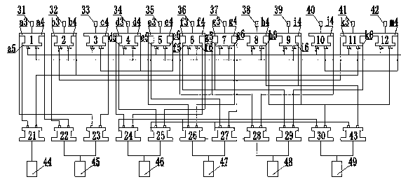
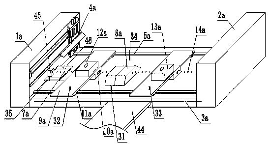
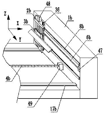
[0047] like Figures 1 to 3As shown, a drop molding machine control system includes a weak current control system and a strong current control system, and the weak current control system includes a signal processor A1, a signal processor B2, a signal processor C3, a signal processor D4, and a signal processor E5, signal processor F6, signal processor G7, signal processor H8, signal processor I9, signal processor J10, signal processor K11 and signal processor M12, described heavy current control system comprises relay A21, relay B22, Relay C23, relay D24, relay E25, relay F26, relay G27, relay H28, relay I29, relay J30 and relay K43, said signal processor A1 is provided with a first signal transmission pile Aa3, a second signal transmission pile Aa4 and The third signal transmission pile a5, the signal processor B2 is provided with the first signal transmission pile Bb3 and the second signal transmission pile Bb4, the signal processor C3 is provided with the first signal transm...

Embodiment 2

[0050] like Figures 1 to 3 As shown, a drop molding machine control system includes a weak current control system and a strong current control system, and the weak current control system includes a signal processor A1, a signal processor B2, a signal processor C3, a signal processor D4, and a signal processor E5, signal processor F6, signal processor G7, signal processor H8, signal processor I9, signal processor J10, signal processor K11 and signal processor M12, described heavy current control system comprises relay A21, relay B22, Relay C23, relay D24, relay E25, relay F26, relay G27, relay H28, relay I29, relay J30 and relay K43, said signal processor A1 is provided with a first signal transmission pile Aa3, a second signal transmission pile Aa4 and The third signal transmission pile a5, the signal processor B2 is provided with the first signal transmission pile Bb3 and the second signal transmission pile Bb4, the signal processor C3 is provided with the first signal trans...

Embodiment 3

[0057] like Figures 1 to 3As shown, a drop molding machine control system includes a weak current control system and a strong current control system, and the weak current control system includes a signal processor A1, a signal processor B2, a signal processor C3, a signal processor D4, and a signal processor E5, signal processor F6, signal processor G7, signal processor H8, signal processor I9, signal processor J10, signal processor K11 and signal processor M12, described heavy current control system comprises relay A21, relay B22, Relay C23, relay D24, relay E25, relay F26, relay G27, relay H28, relay I29, relay J30 and relay K43, said signal processor A1 is provided with a first signal transmission pile Aa3, a second signal transmission pile Aa4 and The third signal transmission pile a5, the signal processor B2 is provided with the first signal transmission pile Bb3 and the second signal transmission pile Bb4, the signal processor C3 is provided with the first signal transm...


PUM


Abstract

The invention relates to a drip molding machine control system and a drip molding machine control method. A weak current control system comprises a signal processor A, a signal processor B, a signal processor C, a signal processor D, a signal processor E, a signal processor F, a signal processor G, a signal processor H, a signal processor I, a signal processor J, a signal processor K and a signalprocessor M; a strong current control system comprises a relay A, a relay B, a relay C, a relay D, a relay E, a relay F, a relay G, a relay H, a relay I, a relay J and a relay K. Signals are sent to the relays by means of the signal processors, and the relays automatically control the cooperative movement of all devices; compared with the traditional numerical control drip molding machine, the control system is higher in accuracy, intuitive in operation and high in degree of automation, replaces the traditional manual work, greatly increases the efficiency of the drip molding industry, and islow in threshold for use.

Description

technical field [0001] The invention belongs to the technical field of plastic dropping, and in particular relates to a control system and method for a plastic dropping machine. Background technique [0002] Drop plastic is currently one of the few products that still uses manual production for most of the craftsmanship. Its main raw material is to dissolve PVC paste resin in DOP and other fats, and add color paste to form a paste resin mixture of different colors. Drop the paste resin mixture of different colors into the aluminum mold, brass mold, electroforming or silicone mold, and heat it to above 170°C, the PVC paste resin and DOP and other lipids undergo a chemical reaction, and become solid and color Rich, three-dimensional products. [0003] At present, some enterprises still use the traditional manual plastic dropping method when producing plastic drop crafts. In addition, there is no unified heating standard, and it is difficult to guarantee the quality of handi...

Claims


Application Information

Patent Timeline
IPC IPC(8): B29C41/22B29C41/52
CPCB29C41/22B29C41/52Y02P90/02
Inventor 魏依光
Owner 遂宁市金虹机械厂
Why Eureka
Try Eureka