
Welding and correcting dual-purpose base

A dual-purpose, sliding seat technology, used in welding equipment, welding equipment, auxiliary welding equipment, etc., can solve the problems of unsuitable batch calibration, troublesome transfer, low degree of automation, etc., to shorten the production cycle and facilitate the application of welding torches. Welding, high degree of automation effect

Inactive Publication Date: 2019-01-01
SUIZHOU ZHUFENG STEEL STRUCTURE ENG
View PDF1 Cites 0 Cited by
  • Summary
  • Abstract
  • Description
  • Claims
  • Application Information

AI Technical Summary

Problems solved by technology

The traditional I-shaped steel structure or U-shaped steel structure is directly placed on the welding frame, and then welded along the length direction of the I-shaped steel structure or U-shaped steel structure by a welding machine. After the welding is completed, due to the existence of certain welding Deformation needs to be corrected in a timely manner. The existing factories use the calibration machine for calibration, that is, the welded I-shaped steel structure or U-shaped steel structure needs to be transported to the calibration machine for calibration, while the I-shaped steel structure or U-shaped steel structure The steel structure itself is bulky, cumbersome, and difficult to transfer, resulting in a longer processing cycle for the I-shaped steel structure or U-shaped steel structure, and the production efficiency has not been further improved.
[0003] For example, the Chinese patent application No. 201310350804.X proposes an H-shaped steel assembly welding and straightening machine with a welding deformation correction device, including an assembly and assembly device, a welding forming device, and a welding deformation correction device. The welding deformation correction device includes a longitudinal adjustment component. and the horizontal adjustment assembly; the longitudinal adjustment assembly includes an eccentric shaft, a ratchet wheel located at one end of the eccentric shaft, and a pressure roller located at the other end of the eccentric shaft. With the above structure, the vertical adjustment assembly and the lateral adjustment assembly can be adjusted separately so that the adjustment of the H-shaped steel can be achieved. The purpose of adjusting the correction amount, however, the all-in-one machine involved in this application still requires manual operation, and the degree of automation is relatively low. Manual adjustment and adjustment of the distance between the pressure roller and the driving wheel cannot guarantee the accuracy of the size, which will affect the correction. Effect, can not further improve production efficiency, not suitable for batch correction

Method used


Image

  • Welding and correcting dual-purpose base
  • Welding and correcting dual-purpose base
  • Welding and correcting dual-purpose base

Examples


Embodiment 1

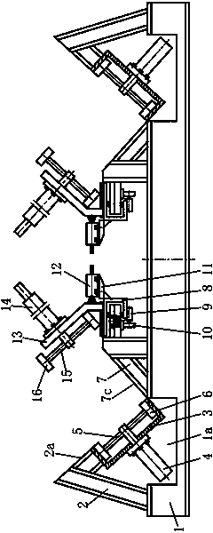
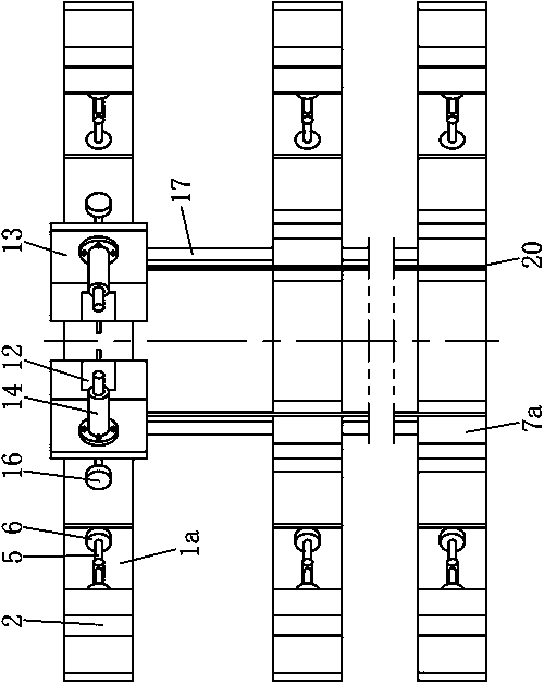
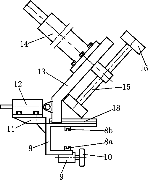
[0035] Embodiment one: if Figure 6 , Figure 7 and Figure 8 As shown, it is mainly aimed at the welding and correction of U-shaped steel structure 21. The working process is as follows: the initial state is as follows Figure 6 As shown, the lower positioning correction wheel 6 is placed in the U-shaped seat 3, and the lower positioning correction wheel 6 is flush with the supporting surface 2a. After the plate of the U-shaped steel structure 21 is initially spot-welded, it is erected on a multi-row base arranged in parallel. On the beam 1, place the main part of the U-shaped steel structure on the outer corner frame 2 and the lower positioning correction wheel 6, and place the side part of the U-shaped steel structure 21 on the retaining surface 7c, and then insert the welding torch into the U-shaped steel The joints of the corners of the structure 21 are welded, using an automatic welding machine to move along the length direction of the U-shaped steel structure 21 to co...

Embodiment 2

[0036] Embodiment two: if Figure 9 , Figure 10 and Figure 11 As shown, it is mainly aimed at the I-shaped steel structure 22, and the working process is as follows: the plate of the I-shaped steel structure 22 to be welded is initially spot-welded, and then the main part of the I-shaped steel structure 22 is placed on the supporting surface 2a , and make the side of the I-shaped steel structure 22 against the retaining surface 7c, then the welding torch can be inserted into the corner of the inner side of the I-shaped steel structure 22 for welding, and the automatic welding machine can be used to weld along the side of the I-shaped steel structure 22. The movement of the length direction of the steel structure 22, thereby completing the overall welding process to the I-shaped steel structure 22; after the welding is completed, the welding torch is withdrawn, and the lower drive cylinder 4 is started, so that the push-down shaft 5 drives the lower positioning correction wh...


PUM


Abstract

The invention relates to a welding and correcting dual-purpose base. The base includes multiple row of foundation beams arranged in parallel. The foundation beams are arranged in parallel in at leastthree rows. The multiple parallelly-arranged rows of the foundation beams can adapt to the length of an I-shaped steel structure or a U-shaped steel structure, and can also adapt to I-shaped steel structures or U-shaped steel structures of different specifications, and meet actual welding and correcting requirements. Accommodating grooves are symmetrically disposed on both sides of each of the foundation beams; left and right ends of each of the foundation beams are symmetrically connected with outer corner brackets; inner corner brackets are symmetrically connected to the middle of each of the foundation beams; lower positioning pushing devices are disposed inside the accommodating grooves; the lower positioning pushing devices are fixedly connected with the outer corner brackets and thefoundation beams; and upper slip correcting devices are mounted on the inner corner brackets. The base has the advantages of reasonable structural design, high degree of automation and high stability,can be used for submerged arc welding of steel structures, facilitates welding of welding guns, can automatically correct the steel structures after welding, makes the correcting efficiency greatly improve, makes transshipment of the steel structure avoid, and makes a production cycle of the steel structure shorten.

Description

technical field [0001] The invention relates to the technical field of steel structure production and processing, in particular to a dual-purpose seat for welding and correction. Background technique [0002] As we all know, steel structures play an important role in buildings, and different structural designs of steel structures will make the building's shape and performance more unique. During production and processing, the steel structure must go through raw material cutting, assembly, submerged arc welding, calibration, shearing drilling, manual welding and forming, shot blasting and painting before it can finally become a steel structure product. Before submerged arc welding, it is necessary to conduct preliminary spot welding on the plates of the steel structure, so that the preliminary positioning and connection between the plates can be carried out. The main purpose is to prepare for submerged arc welding and facilitate welding by welding machines. The traditional...

Claims


Application Information

Patent Timeline
Patent Type & Authority Applications(China)
IPC IPC(8): B23K37/04B23K9/18B21D1/14B21D1/02
CPCB23K37/0426B21D1/02B21D1/145B23K9/18B23K37/0461
Inventor 何宗虎
Owner SUIZHOU ZHUFENG STEEL STRUCTURE ENG
Learn More