A drilling fluid mixing and cleaning stirring device and its control method

A technology of a stirring device and drilling fluid, which is applied in the field of drilling engineering, can solve the problems of high output power of the motor, limited conveying capacity of the impeller, and troublesome process, and achieves the effect of enhancing the conveying capacity and the mixing capacity.

Active Publication Date: 2020-04-24
SICHUAN ZHONGCHUANG PETROLEUM EQUIP CO LTD
View PDF7 Cites 0 Cited by
  • Summary
  • Abstract
  • Description
  • Claims
  • Application Information

AI Technical Summary

Problems solved by technology

[0004] The utility model patent with the application number CN201720166926.7 discloses a sprinkler impeller. This sprinkler impeller basically solves the above problems, but the process is troublesome and the number of sprinklers is limited. This sprinkler impeller follows the previous impeller style, and the blades pass through the mounting plate. Connected with the infusion tube, the liquid above and below the mounting plate will not be stirred, and the delivery capacity of the impeller is limited. Since the nozzle is directly assembled and welded on the infusion tube, if the impeller rotates fast, the water column cannot flow after the nozzle sprays water because the speed is too fast. If The rotating speed is slow, and the agitation effect on the liquid is not good, which is not solved by the nozzle impeller.
[0005] The utility model patent with the application number CN201720226751.4 discloses a drilling fluid mixing and cleaning device. Its working condition is that the liquid presents a swirl-like liquid flow when stirring, and a fountain-like liquid flow when mixing. The direction of output is the same, the impact force of the liquid prevents the rotation of the impeller, the impeller needs a larger torque to work, and the output power of the motor is larger

Method used


Image

  • A drilling fluid mixing and cleaning stirring device and its control method
  • A drilling fluid mixing and cleaning stirring device and its control method
  • A drilling fluid mixing and cleaning stirring device and its control method

Examples


Embodiment 1

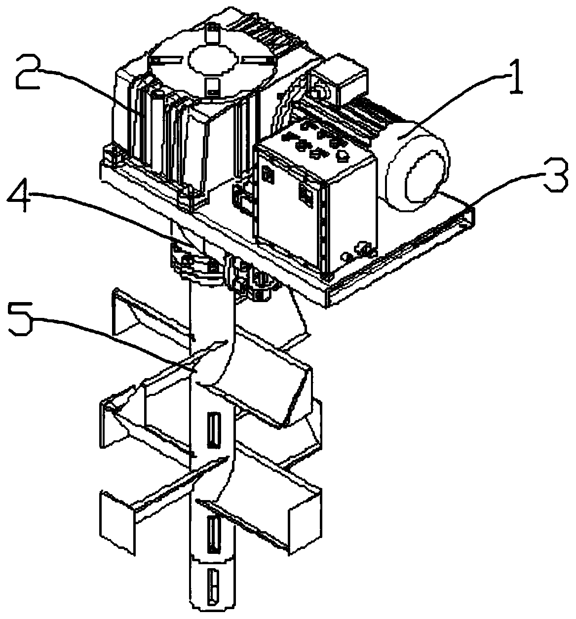
[0049] Such as Figure 1-Figure 4 and Figure 9 As shown, a drilling fluid mixing and cleaning stirring device includes a driving transmission mechanism, a base 3 and a liquid inlet stirring mechanism, the driving transmission mechanism is arranged on the upper surface of the base 3, and the liquid inlet stirring mechanism is arranged on the lower surface of the base 3 , and the liquid inlet stirring mechanism is connected with the drive transmission mechanism; the drive transmission mechanism includes an explosion-proof motor 1 and a gearbox 2 that are fixedly arranged on the upper surface of the base 3, the explosion-proof motor 1 is connected with the gearbox 2, and the explosion-proof motor 1 is connected with the gearbox 2. The output shaft of the gearbox 2 passes through the base 3 and is connected to the liquid inlet stirring mechanism; the liquid inlet stirring mechanism includes a mixing transmission device 4 and a stirring rod 5, and the mixing transmission device 4 ...

Embodiment 2

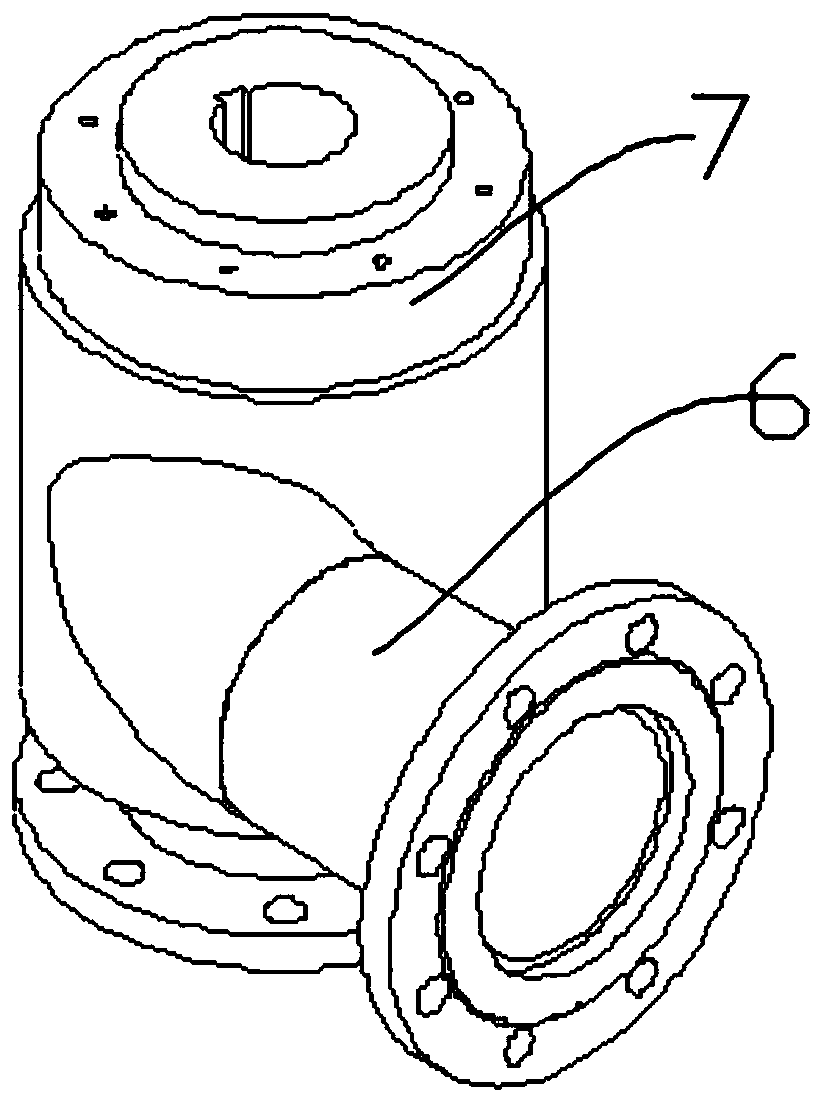
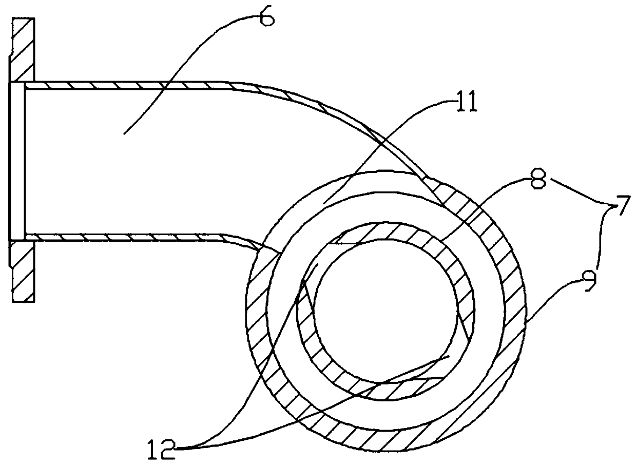
[0052] Such as Figure 4 As shown, in this embodiment, on the basis of Embodiment 1, a plurality of second liquid inlets 12 are evenly opened on the side wall of the inner rotating body 8 , and between the outer wall of the inner rotating body 8 and the inner wall of the outer casing 9 A cavity 15 is provided. There are multiple second liquid inlets 12, which can enhance the liquid inlet efficiency in the inner rotating body 8. At the same time, a cavity 15 is set between the inner rotating body 8 and the outer shell 9, which further increases the liquid intake in the inner rotating body 8. The liquid feeding rate increases the speed of mixing and agitation.

Embodiment 3

[0054] Such as Figure 5-Figure 7 As shown, this embodiment is based on Embodiment 2. The stirring rod 5 includes a first liquid inlet shaft tube 17, and an impeller group is connected to the first liquid inlet shaft tube 17. The first liquid inlet shaft tube 17 A plurality of spray slits 18 are evenly opened on the top, and the liquid outlet direction of the spray slits 18 is the same as the direction of the stirring working surface of the impeller. The layer hole 28 and the outer layer hole 29 on the outer pipe wall of the first liquid inlet shaft tube 17, the first upper edge 30 of the inner layer hole 28 is vertically higher than the second upper edge 31 of the outer layer hole 29, and the inner The first lower edge 32 of the layer hole 28 is vertically higher than the second lower edge 33 of the outer layer hole 29 .

[0055] By setting the spray slot 18, the previous way of setting the nozzles has been changed, which can better achieve the effect of cleaning the grit. I...


PUM


Abstract

The invention discloses a drilling fluid mixing and cleaning stirring device and a control method thereof. The drilling fluid mixing and cleaning stirring device includes a driving transmission mechanism, a base and a liquid inlet stirring mechanism. The liquid inlet stirring mechanism includes a mixing transmission device and a stirring rod. The mixing transmission device It includes a liquid inlet pipe and a rotating mechanism. The rotating mechanism includes an inner rotating body and an outer casing. The inner rotating body and the outer casing are rotatably connected by bearings. The outer casing is provided with a first liquid inlet. The side wall of the inner rotating body is provided with a second liquid inlet, the second liquid inlet is a conical liquid inlet, and the small end of the second liquid inlet faces the outside of the inner rotating body, the second liquid inlet The axis of the liquid port intersects the axis of the inner rotating body, and the inner rotating body is connected with a stirring rod through a liquid outlet pipe. By using different control methods, the present invention can realize three functions of stirring, mixing and cleaning, and the stirring effect is good, cleaning Sand is convenient, and the torque of the impeller is small when mixing, which saves energy.

Description

technical field [0001] The invention relates to the technical field of drilling engineering, in particular to a drilling fluid mixing, cleaning and stirring device and a control method thereof. Background technique [0002] The mixing and stirring of drilling fluid is an indispensable process in the solids control system. The mixing and stirring is mainly to prevent the drilling fluid from settling. When the drilling fluid density is too small (too high), the drilling fluid is aggravated (diluted) and then the drilling fluid is stirred to make the drilling fluid density in the tank basically constant. The general stirring impeller only has a stirring effect, and cannot fully stir and mix the grit at the bottom of the tank, so that the stirring effect is not ideal; in addition, the tank body in the prior art is generally a cuboid, and the drilling fluid in the corner cannot be stirred and mixed for a long time. If it cannot participate in the circulation operation of the ent...

Claims


Application Information

Patent Timeline
Patent Type & Authority Patents(China)
IPC IPC(8): B01F7/18B01F15/00B01F15/02E21B21/06
CPCE21B21/062B01F27/11252B01F27/2123B01F27/191B01F27/88B01F27/90B01F35/324B01F35/33B01F35/3204B01F35/712B01F35/7179
Inventor 李舒婷
Owner SICHUAN ZHONGCHUANG PETROLEUM EQUIP CO LTD
Why Eureka
Try Eureka