Automatic peeling machine

A peeling machine and automatic technology, applied in peeling appliances, household appliances, applications, etc., can solve the problems of loss of nutrients and low peeling efficiency of fruits and vegetables, and achieve the effect of ensuring freshness and improving the removal rate

Inactive Publication Date: 2019-01-01
WUHU YUANMA AUTOMATION EQUIP CO LTD
View PDF6 Cites 0 Cited by
  • Summary
  • Abstract
  • Description
  • Claims
  • Application Information

AI Technical Summary

Problems solved by technology

[0003] Aiming at the deficiencies in the prior art, the present invention provides an automatic peeler, which solves the problem of low peeling efficiency of the manual peeler and the loss of nutrients in the fruits and vegetables by mechanical peelers when peeling long strips of fruits and vegetables. For the problem of losing a part, the present invention adopts the following technical solution to solve the technical problem: including the base, 4 motors are arranged inside the base, 2 of the 4 motors are located in the front and rear direction of the left end of the base, and the other 2 are located in the base In the front and rear direction of the right end of the seat, the motors in front of the left end and the front of the right end rotate clockwise, and the motors behind the left end and the rear of the right end rotate counterclockwise. The top end is covered with a sponge ring, and there are 2 cylinders in the middle of the top of the base. The 2 cylinders are respectively located at the front end and the rear end of the top of the base. The 2 cylinders are respectively equipped with torsion springs, and the torsion springs are connected with a peeling mechanism. , the left end of the top of the base is provided with an inlet slot, the right end of the top of the base is provided with an outlet slot, the right side of the outlet slot is provided with a conveyor belt, and the front of the conveyor belt is provided with a finished box

Method used


Image

  • Automatic peeling machine
  • Automatic peeling machine
  • Automatic peeling machine

Examples


Embodiment Construction

[0012] In order to deepen the understanding of the present invention, the present invention will be further described below in conjunction with the examples, which are only used to explain the present invention, and do not constitute a limitation to the protection scope of the present invention.

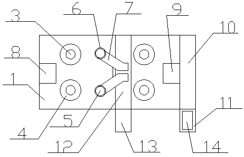
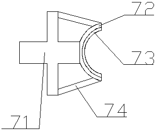
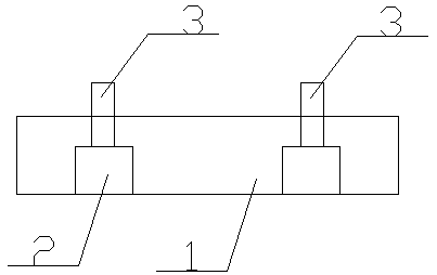
[0013] Such as Figure 1-3 Shown, the present embodiment provides a kind of automatic peeling machine, comprises base 1, and base 1 interior is provided with 4 motors 2, and 2 in 4 motors 2 are positioned at base 1 left end front and rear direction, and other 2 Located in the front and rear direction of the right end of the base 1, the motor 2 in front of the left end and the front of the right end rotates clockwise, and the motor 2 behind the left end and the rear of the right end rotates counterclockwise. The motor 2 is connected with a rotating shaft 3, and the motor 2 drives the rotating shaft 3 to rotate. The top of the rotating shaft 3 protrudes upwards through the top of the b...


PUM


Abstract

The invention provides an automatic peeling machine including a base, 4 motor are arranged inside that base, two of the four motors are located in the front-rear direction of the left end of the base,2 in the front-rear direction of the right end of the base, a shaft is connected to the motor, the top end of the rotating shaft protrudes upward through the top end of the base, a sponge ring is sleeved at the top of the rotating shaft, 2 cylinders are arranged at the middle position of the top of the base, 2 cylinders are respectively located at the front end and the rear end of the top of thebase, torsion springs are respectively arranged on the two cylinders, a peeling mechanism is connected to the torsion springs, a left end of that top of the base is provide with an inlet groove, a right end of the top of the base is provided with an outlet groove, a conveyor belt is arranged on the right side of the outlet groove, and a finished product box is arranged in front of the conveyor belt. By arranging arc-shaped soft block and arc-shaped blade, the machine can automatically adapt to the size of the fruit, and the peel removal rate of the cylindrical fruit and vegetable is improved.

Description

technical field [0001] The invention relates to the technical field of automatic processing, in particular to an automatic peeling machine. Background technique [0002] Vegetable and fruit peeling machine refers to using a machine to imitate the peeling action of humans to remove the peel of fruits and vegetables, which is convenient for subsequent processing and eating, and improves the quality. There are many types of vegetable and fruit peeling machines on the market, such as manual peeling machines and mechanical peeling machines. , when this type of peeling machine peels long strips of fruits and vegetables such as carrots, cucumbers, etc., the peeling efficiency of the manual peeler is low, while the mechanical peeling machine needs to insert a shaft into the fruits and vegetables, through a fixed Vegetables and fruits can only be peeled after the peeling, which will cause the loss of part of the nutrients in the vegetables and fruits. Therefore, it is very necessary ...

Claims


Application Information

Patent Timeline
Patent Type & Authority Applications(China)
IPC IPC(8): A47J17/16
CPCA47J17/16
Inventor 胡世珍
Owner WUHU YUANMA AUTOMATION EQUIP CO LTD
Why Eureka
Try Eureka