Plastic product display table
A technology for plastic products and display stands, applied in the field of display stands, can solve the problem of not being able to store and protect multiple exhibits at the same time, and achieve the effect of avoiding replacement and reducing damage
- Summary
- Abstract
- Description
- Claims
- Application Information
AI Technical Summary
Problems solved by technology
Method used
Image
Examples
specific Embodiment approach 1
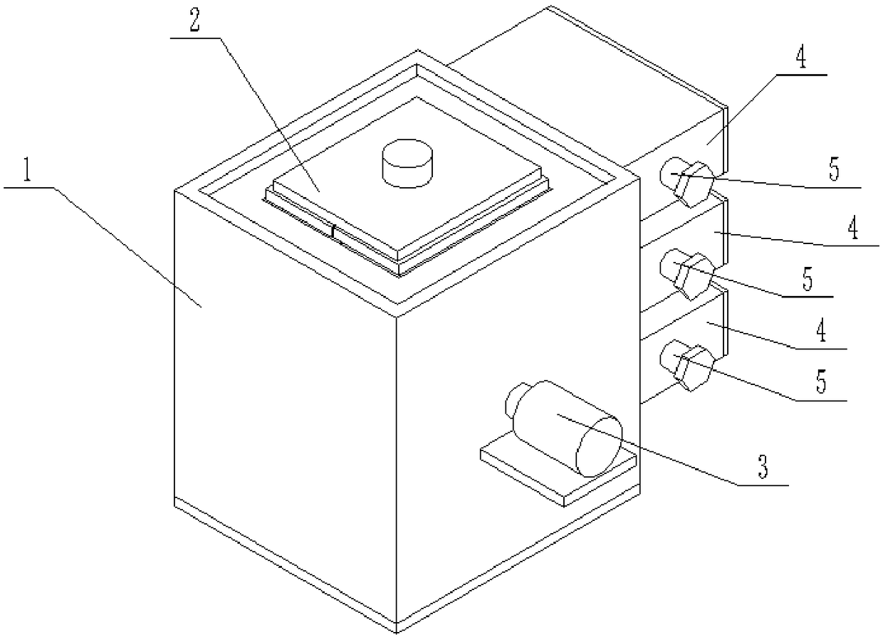
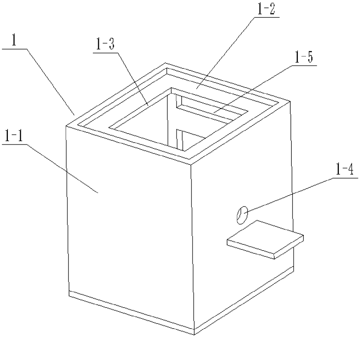
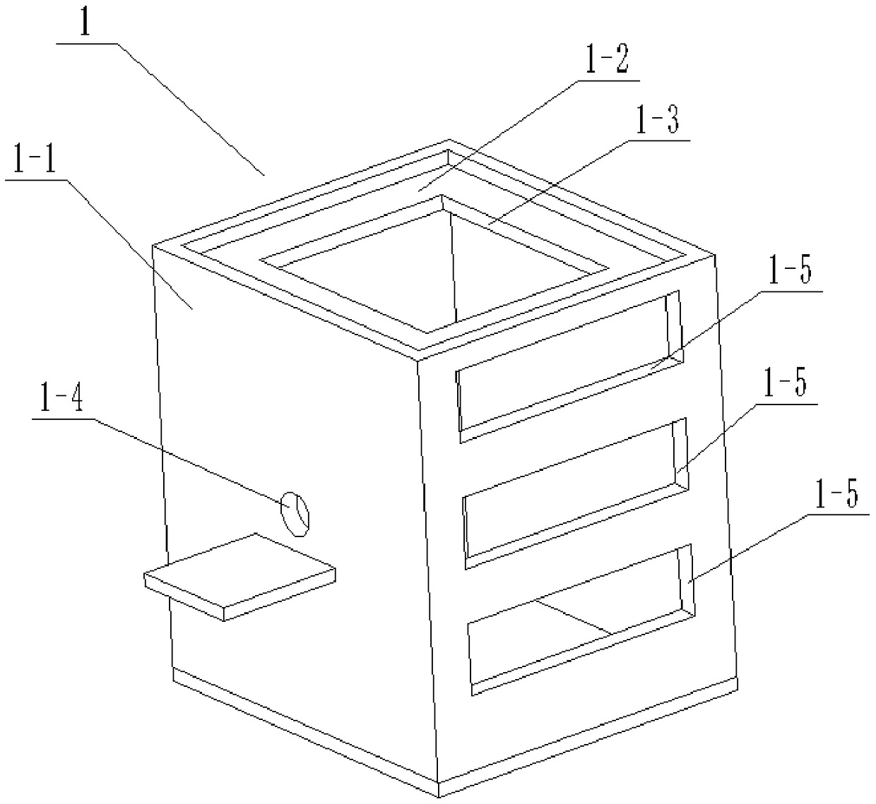
[0027] Such as Figure 1 to Figure 10 As shown, a display stand for plastic products, a display stand for plastic products, includes a display stand body 1, a display fixing base 2, a lifter 3, a display case 4 and an adjustment protector 5, and the display stand body 1 includes Box body 1-1, upper end plate 1-2, slotted hole 1-3, rotating round hole 1-4 and a plurality of spare opening slots 1-5, upper end plate 1-2 is fixedly connected to the upper end of box body 1-1 , the slot hole 1-3 is set at the center of the upper end plate 1-2, the rotating round hole 1-4 is set at the right end of the box body 1-1, and a plurality of through-slots 1-5 are set in the box body sequentially from top to bottom The front end of 1-1, the slotted hole 1-3, the rotating round hole 1-4 and a plurality of spare through slots 1-5 are all connected to the inside of the box body 1-1, and the right end of the inner wall of the box body 1-1 is provided with two longitudinal T-shaped slide rail; ...
specific Embodiment approach 2
[0031] Such as Figure 1 to Figure 10 As shown, this embodiment will further illustrate Embodiment 1, and the described exhibition box 4 also includes a T-shaped slide plate 4-5, a loading plate 4-6, an exhibit fixing block 4-7, a push slider 4-11 and Manual push block 4-12, T-shaped slide plate 4-5 is slidably connected to T-shaped chute 4-3, loading plate 4-6 is fixedly connected to the upper side of the rear end of T-shaped slide plate 4-5, exhibit fixed block 4 -7 is fixedly connected to the center of the upper end of the loading plate 4-6, and the push slider 4-11 is fixedly connected to the lower side of the front end of the T-shaped slide plate 4-5, and the push slider 4-11 is slidably connected to the rectangular slot 4-4 Inside, the manual push block 4-12 is fixedly connected to the lower end of the push slide block 4-11. By pushing and withdrawing the manual pushing block 4-12 and pushing the sliding block 4-1, the T-shaped slide plate 4-5, the loading plate 4-6 and...
specific Embodiment approach 3
[0032] Such as Figure 1 to Figure 10 As shown, this embodiment further explains the second embodiment. The display fixing base 2 includes an exhibit bottom plate 2-1, an exhibit fixing platform 2-2 and a positioning rectangular groove 2-3, and the exhibit fixing platform 2-2 is fixedly connected At the center of the upper end of the exhibit base plate 2-1, a positioning rectangular groove 2-3 is arranged at the center of the lower end of the exhibit base plate 2-1, and the gap between the positioning rectangular groove 2-3 matches the exhibit fixing block 4-7. The exhibit bottom plate 2-1 is lifted and lowered by the lifter 3, and then the positioning rectangular slot 2-3 is inserted into the exhibit fixing block 4-7, which is convenient for switching and storing multiple exhibits.
PUM
 Abstract
Description
Claims
Application Information
 - R&D Engineer
- R&D Manager
- IP Professional
- Industry Leading Data Capabilities
- Powerful AI technology
- Patent DNA Extraction
Browse by: Latest US Patents, China's latest patents, Technical Efficacy Thesaurus, Application Domain, Technology Topic, Popular Technical Reports.
© 2024 PatSnap. All rights reserved.Legal|Privacy policy|Modern Slavery Act Transparency Statement|Sitemap|About US| Contact US: help@patsnap.com


