Time-resolved spectrum and lifetime measurement module and device

A measurement module and spectrometer technology, applied in the field of optical instrument manufacturing and instrument analysis, can solve the problems of difficult detection of materials, low cost, and limited time resolution of time-resolved detection methods

Pending Publication Date: 2018-12-28
武汉能斯特科技有限公司
View PDF12 Cites 3 Cited by
  • Summary
  • Abstract
  • Description
  • Claims
  • Application Information

AI Technical Summary

Problems solved by technology

[0006] However, in the disclosed technology, the speed of the existing mechanical chopper is below 200 rpm, although the motor speed in some studies can reach more than 2000 rpm, but its load is limited, which limits the time based on the rotation of the motor The time resolution of the resolution detection method is difficult to detect for materials with excited state lifetimes below the microsecond level
[0007] The patent (CN201710042628.1) discloses a detection method for fluid delayed luminescence, which uses the movement of the fluid to shift the position of the sample to achieve time-resolved detection. However, the flow rate of the fluid is limited, requiring a large pressure and a very fine The pipeline realizes the high-speed flow of the fluid, and this method is difficult to achieve the detection of microsecond delay
[0008] The patent (CN201711110647.X) discloses a method of measuring life using an image sensor, which does not require pulse and phase-locked control, and has ultra-low cost. However, in the case of existing motor technology, its time resolution is difficult to reach microseconds the following

Method used


Image

  • Time-resolved spectrum and lifetime measurement module and device
  • Time-resolved spectrum and lifetime measurement module and device
  • Time-resolved spectrum and lifetime measurement module and device

Examples


Embodiment 1

[0062] Implementation example 1, a life measurement module and device

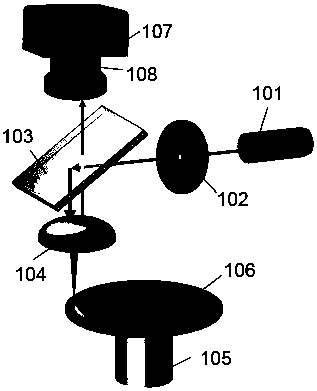
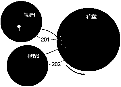
[0063] as attached figure 1 As shown, the light output by the light source 101 passes through the pinhole 102, is reflected by the dichroic mirror 103, and is focused on a point on the turntable 106 through the objective lens 104. The turntable is covered with a sample. When the motor 105 drives the turntable to rotate, the delayed luminescence of the sample It will be released in a region other than the excitation point, and a part of the light will pass through the objective lens 104 and the dichroic mirror 103 , and then be focused on the image sensor 107 by the lens 108 .

[0064] The light source 101, the pinhole 102, the dichroic mirror 103, the objective lens 104, the motor 105, and the turntable 106 constitute a measurement module, which is used in conjunction with the image sensor 107 and the lens 108 in this implementation example.

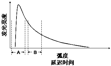
[0065] During life measurement:

[0066] The motor drives the...

Embodiment 2

[0079] Implementation example 2, a kind of life measuring device

[0080] as attached Figure 4As shown, the light output by the light source 101 passes through the pinhole 102, is reflected by the dichroic mirror 103, and is focused on a point on the turntable 106 through the microscope objective lens 109. The turntable is covered with samples. When the motor 105 drives the turntable to rotate, the delay of the sample The luminescence will be released in areas other than the excitation point, and a part of the luminescence will pass through the microscope objective lens 109 , the dichroic mirror 103 and the filter 110 , and then be focused into the image sensor 107 by the lens 108 .

[0081] According to the emission wavelength of a specific sample, an appropriate filter 110 can be selected, such as band pass, long wave pass, short wave pass, etc. to reduce the interference of scattered light.

[0082] The principle of measuring the lifetime of the device is consistent with ...

Embodiment 3

[0083] Implementation example 3, a kind of lifetime and time-resolved spectrum measuring device

[0084] as attached Figure 5 As shown, the light output by the light source 101 passes through the pinhole 102, is reflected by the dichroic mirror 103, and is focused on a point on the turntable 106 through the microscope objective lens 109. The turntable is covered with samples. When the motor 105 drives the turntable to rotate, the delay of the sample The luminescence will be released in areas other than the excitation point, and a part of the luminescence will pass through the microscope objective lens 109, the dichroic mirror 103, and exit from the aperture 111. Then, the semi-reflective half lens 112 makes a part of this beam of light pass through and a part of it reflect , wherein the transmitted light is focused on the image sensor 107 by the lens 108 , and the reflected light enters the spectrometer 115 through the fiber collimator 113 and the optical fiber 114 .

[0085...


PUM


Abstract

The invention discloses a measurement module. The module uses a motor to drive an excited sample to rotate in space, so that illuminating signals with different delay times are spatially separated, and then the micro space is enlarged by a lens, a specific spatial domain is also selected for observation, and the time-resolved detection can be achieved. Through the combined use of the module and animage sensor, the lifetime of the excited state can be measured; and through the combined use of the module and a spectrograph, the time-resolved spectrum detection can be implemented. According to the resolution of optical imaging and the rotating speed of an existing motor, the time resolution of the device can reach a nanosecond level, and most fluorescence lifetime measurements can be satisfied. The method can measure the lifetime of the excited state by using a steady-state light source with arbitrary wavelength, does not need expensive pulsed light sources and detectors, does not need aphase-locked control operation, and has a lower cost.

Description

technical field [0001] The invention relates to the time-resolved photoluminescence spectrum and lifetime measurement method and the manufacture and application of related instruments and devices. It belongs to the field of optical instrument manufacturing and instrument analysis. Background technique [0002] In the phenomenon of photoluminescence, molecules are excited by light to transition to an excited state, and the molecules in the excited state can return to the ground state by releasing photons, that is, the fluorescence or phosphorescence of the molecule. The excited state of the molecule has a lifetime, that is, the molecule in the excited state will release photons to return to the ground state after a period of time, and the lifetime of the excited state of different molecules is different. The longer the lifetime of the excited state of a molecule, the longer its luminescence duration. Normally, the fluorescence lifetime of molecules is on the order of nanosec...

Claims


Application Information

Patent Timeline
IPC IPC(8): G01J3/28G01J3/02G01N21/64
CPCG01J3/0208G01J3/0218G01J3/2889G01N21/6408G01N2021/641
Inventor 朱泽策
Owner 武汉能斯特科技有限公司
Why Eureka
Try Eureka